Verification Manual
Verifies the validity of the bearing elements provided in Bearings.
Introduction
The verification of two machinery bearings, deep groove ball bearing (DGBB) and cylindrical roller bearing (CRB), is achieved by comparing the results of their respective full Multibody Dynamics (MBD) representation against their reduced order model (ROM).
The MBD representation defines both bearing rings (inner and outer) and each rolling element as a rigid body with an accurate graphical representation. Rigid body contact is defined between the graphics of every rolling element and the two bearing rings. The cage, what keeps the rolling elements in place, is replaced by kinematic constraints to keep the distance of the rolling elements constant during rotation.
The ROM, on the other hand, uses an analytical formulation of calculating bearing forces. This is implemented using general force element (Gforce) with a MotionSolve subroutine (GFOSUB). The details of the ROM is described in Bearings.
For the verification, each model approach will be used with the same bearing parameters. Differences occur only if the model methodology requires it. Contact stiffness between the rings and rolling elements in the MBD model is calculated similarly to the analytical formulation inside the ROM model. For ball bearings (point contact) the contact stiffness is calculated according to the Hertzian approach and for roller bearings (line contact) according to Palmgren formula. Small damping proportional to stiffness is introduced to simulate the material and oil/grease damping effects in the contact areas. Damping effects due to oil slushing is ignored. The bearings are connected to a shaft on the inner ring and to the ground on the outer ring.
Test Subjects
The first test subject is a standard 6005 deep groove ball bearing with its parameters given by the table below.
| DGBB 6005 | ||
|---|---|---|
| Parameter | Value | Units |
| number_of_rollers | 10 | - |
| pitch_diameter | 36.0 | mm |
| width | 12.0 | mm |
| inner_diameter | 25.0 | mm |
| inner_shoulder_diameter | 32.04 | mm |
| inner_density | 7.85e-6 | Kg/mm^3 |
| outer_diameter | 47.0 | mm |
| outer_shoulder_diameter | 39.96 | mm |
| outer_density | 7.85e-6 | Kg/mm^3 |
| roller_diameter | 6.746 | mm |
| roller_density | 7.85e-6 | Kg/mm^3 |
| bearing_clearance | 10 | μm |
| inner_race_conformity | 0.52 | - |
| outer_race_conformity | 0.53 | - |
For the ROM model some extra parameters need to be defined shown on the following table.
| NLC parameters (DGBB) | ||
|---|---|---|
| Parameter | Value | Units |
| young_modulus | 210000 | N/mm’^2 |
| poisson_ratio | 0.3 | - |
| damping_force | True | - |
| friction_torque | True | - |
| damping_factor | 0.1 | - |
| static_load_rating | 6.55e3 | N |
| lubricant_viscosity | 80 | cSt |
| lubrication_method | ‘grease’ | - |
For the MBD model it is necessary to define all the input parameters of the contact modeling element. As mentioned in the introduction, the stiffness and damping are theoretically calculated and presented on the following table. The exponent for the Hertzian Point contact is always 1.5. The parameters (na, nc, no) express the fidelity of the rings triamesh. Due to the small clearances in bearings, the graphical tessellation needs to be very fine to obtain realist bearing results.
| Contact parameters (DGBB) | ||
|---|---|---|
| Parameter | Value | Units |
| use_contact_stiffness | True | - |
| damping_factor | 2.5e-5 | - |
| method.stiffness | 730424.83 | N/mm |
| method.exponent | 1.5 | - |
| method.damping | 18.26 | Ns/mm |
| method.dmax | 0.013 | mm |
| method.coulomb_friction | “On” | - |
| method.vd | 110 | mm/s |
| method.md | 0.03 | - |
| method.ms | 0.05 | - |
| method.vs | 100 | mm/s |
| na | 2000 | - |
| nc | 80 | - |
| no | 2 | -- |
The second test subject is a standard NU 1005 cylindrical roller bearing with its parameters given by the table below.
| CRB NU 1005 | ||
|---|---|---|
| Parameter | Value | Units |
| number_of_rollers | 12 | - |
| pitch_diameter | 36.0 | mm |
| width | 13.0 | mm |
| inner_diameter | 25.0 | mm |
| inner_shoulder_diameter | 30.5 | mm |
| inner_density | 7.85e-6 | Kg/mm^3 |
| outer_diameter | 47.0 | mm |
| outer_shoulder_diameter | 38.8 | mm |
| outer_density | 7.85e-6 | Kg/mm^3 |
| roller_diameter | 5.5 | mm |
| roller_length | 5.67 | mm |
| roller_density | 7.85e-6 | Kg/mm^3 |
| bearing_clearance | 20 | μm |
| effective_roller_length | 5 | mm |
The next table entails some extra parameters required for the ROM.
| ROM parameters (CRB) | ||
|---|---|---|
| Parameter | Value | Units |
| axial_constraint | True | - |
| damping_force | True | - |
| friction_torque | True | - |
| damping_factor | 0.15 | - |
| lubricant_viscosity | 80 | cSt |
| lubrication_method | ‘grease’ | - |
For the MBD model it is necessary to define all the input parameters of the contact modeling element. As mentioned in the introduction, the stiffness and damping are theoretically calculated and presented on the following table. The exponent that is used for the Palmgen formulation is 10/9. The parameters (na, nc, no) express the fidelity of the rings triamesh. Due to the small clearances in bearings, the graphical tessellation needs to be very fine to obtain realist bearing results.
| Contact parameters (CRB) | ||
|---|---|---|
| Parameter | Value | Units |
| axial_constraint | True | - |
| use_contact_stiffness | True | - |
| damping_factor | 10e-3 | - |
| method.stiffness | 336980.92 | N/mm |
| method.exponent | 10/9 | - |
| method.damping | 3369.8 | Ns/mm |
| method.dmax | 0.013 | mm |
| method.coulomb_friction | “On” | - |
| method.vd | 110 | mm/s |
| method.md | 0.03 | - |
| method.ms | 0.05 | - |
| method.vs | 100 | mm/s |
| na | 2000 | - |
| nc | 80 | - |
| no | 10 | -- |
As it can be noticed the damping factor here was chosen here a bit higher compared to the DGBB. The extra damping helps in reducing the numerical noise coming from the line contact.
For both, MBD model and ROM, axial_constraint flag is used to prevent axial displacement due to the lack of axial stiffness in the models (lack of flanges on the inner/outer ring).
Experiments
Six different experiments are considered, three for each bearing.
Static Load for DGBB
The first experiment looks at internal bearing deflection or yield due to a static external force acting on the shaft. The yield increases nonlinearly as external load increases. For the DGBB, an external force was applied on the center of the inner ring that acts radially and axially, as shown below. The radial part of the force acts in the y-direction of the local bearing frame of reference, while the axial part is always 0.25 times the radial part and acts in the z-direction.
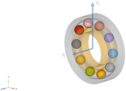
Figure 1.
The following diagram compares the bearing yield between Reduced Order Model and Full MBD model.
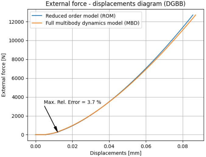
Figure 2.
Both models behave statically very similar, particularly up to the static load rating for the bearing (6550N). Above the static load rating, the results diverge, since the ROM’s equations are derived from empirical data that is only valid up to the static load rating. This is acceptable since bearings should never experience loads above their static load rating in real applications. Up to the static load rating, the relative error is below 4% and measured at low forces. This is expected due to the discontinuous behavior created by the bearing clearances.
Static Load for CRB
For the CRB, the load direction was chosen to be purely radial to the bearing, i.e. in the y-direction of the local bearing frame of reference.
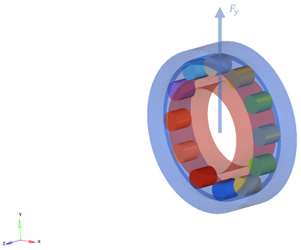
Figure 3.
The following diagram compares the bearing yield between Reduced Order Model and Full MBD model.
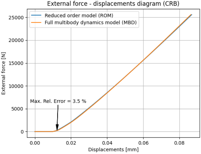
Figure 4.
Similarly to the DGBB example, the maximum error is identified again in the lower range of the external load which is less than 4%. Furthermore, the two models correlate very well even above the static load rating.
Opposed to the DGBB, the slope of the bearing yield is almost linear for the CRB. This is due to the different contact phenomena between those bearings. While the DGBB is experiencing a point contact between rolling elements and rings that spreads into an elliptical contact area, the CRB experiences more of a line contact that spreads into a rectangular shape. In Hertzian Contact methodology, the difference between point and line contact is primarily expressed by the contact exponent (3/2 for point and 10/9 for line contact).
Dynamic Response for DGBB
The third experiment looks at the dynamic response for the DGBB due to an oscillating external load. The bearing response (maximum yield) usually increases when the excitation frequency hits the bearing’s resonance frequency. During this experiment, the amplitude of the external load is kept constant while the excitation frequency slowly changes from 10 to 6000 Hz. Again, there is no rotation in the shaft. The maximum bearing yield is measured for the entire frequency range.
The following diagram shows the frequency response of the DGBB using the ROM and the full MBD model representation.
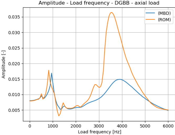
Figure 5.
Both models, ROM and MBD model, showcase similar frequency response. Two regions of critical frequencies behavior can be noticed. The first one is between 824 Hz (ROM) and 949 Hz (MBD), while the second one is between 3559 Hz (ROM) and 3925 Hz (MBD). Frequency wise, the relative error between the ROM and the MBD model is around 9-13%, which is acceptable. Larger differences occur in the magnitude of the response, particularly for larger frequencies. The magnitude of the response is primarily driven by the damping, which is differently implemented for both models.
Better results can be obtained if only a pure radial load is applied, as shown below. Here, the critical frequency ranges from 3071 HZ (MBD) to 3193 Hz (ROM), which results in a relative error of 4%.
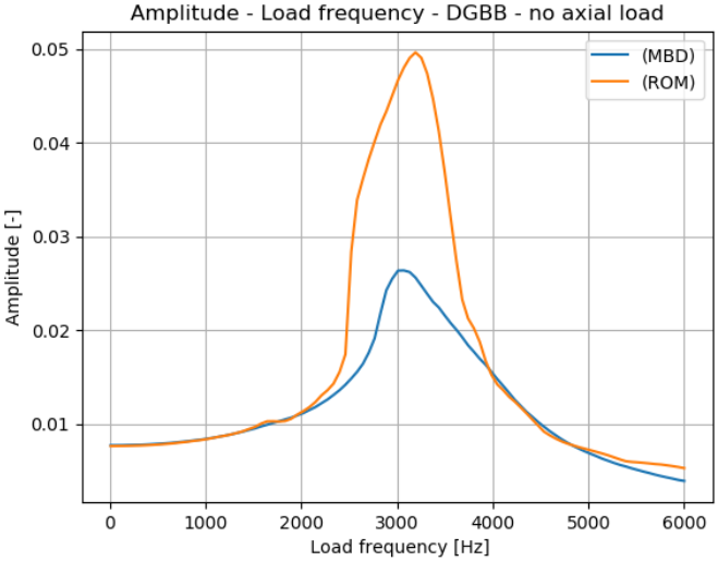
Figure 6.
It should be noted that a bearing’s frequency response changes based on how loads are applied to it. This is primarily due to the highly nonlinear characteristic of the bearing. Both models, ROM and full MBD model, can successfully capture the shift in frequency response due to changes in the direction of the load.
Dynamic Response for CRB
Next, the dynamic response for the CRB due to an oscillating external force in pure radial direction is presented, as shown below. The critical frequency of the CRB is approximately 4000 Hz for both, ROM and MBD model. Even the magnitude is similar in both cases.
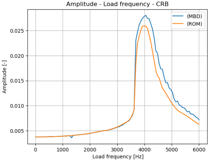
Figure 7.
Fundamental Frequency for DGBB
In the fifth experiment, the fundamental bearing frequencies for DGBB is investigated. Those frequencies are naturally generated by the rolling elements as they pass through the load zone. The external load is constant like the first experiment. The shaft is rotating with a speed of 286.5 rpm (30rad/sec). The transient behavior of the DGBB is shown below in form of relative displacement between inner and outer ring.
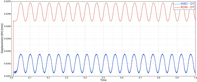
Figure 8. Model comparison in displacement response - DGBB
Both models, ROM and full MBD model, show an oscillation with same frequency that is caused by the rolling elements passing through the loading zone. Although the ROM model does not include rolling elements parts, their theoretical move is calculated inside the force subroutine of the machinery bearings. Here, this calculation is clearly validated.
Looking at the computational performance, we can see that the ROM performs significantly better in a transient analysis compared to the full MBD model.
| Simulation time comparison | ||
|---|---|---|
| Method | Simulation time [sec] | Simulation time [min] |
| ROM | 1.513E+01 | 0.25 |
| MBD | 1.814E+03 | 30.23 |
Fundamental Frequency for CRB
The last experiment looks at the fundamental frequencies of the CRB. The external load is constant similar to the second experiment and the shaft is rotating with a speed of 286.5 rpm (30rad/sec). The transient behavior of the CRB is shown below in form of relative displacement between inner and outer ring. Just as in the previous experiment for the DGBB, the bearing experiences an oscillation with a constant frequency.
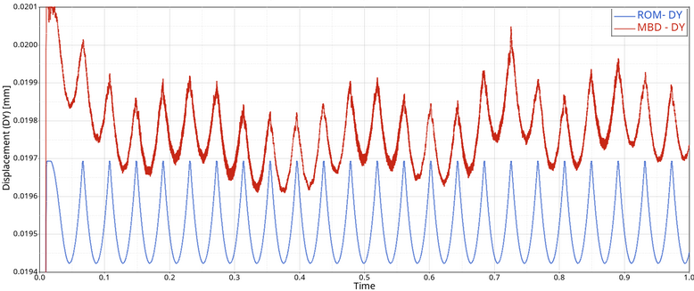
Figure 9.
Again, in term of computational performance the ROM is significantly superior compared to the respective full MBD model for transient analysis.
| Simulation time comparison | ||
|---|---|---|
| Method | Simulation time [sec] | Simulation time [min] |
| ROM | 1.485E+01 | 0.25 |
| MBD | 5.852E+03 | 97.53 |
Conclusion
Comparisons of full Multibody Dynamic (MBD) bearing models against reduced order bearing models (ROMs) from the MSolve API was conducted. The Comparison was first performed on a Deep Groove Ball Bearing (DGBB), followed by a Cylindrical Roller Bearing (CRB). The verification shows that the results of the ROM models are similar to their respective MBD model. Furthermore, it highlights much greater computational performance of ROMs compared to full MBD models.
While the MSolve API includes ROMs for several bearing types, the verification was performed only on two bearing families, ball bearings and roller bearing. The remaining bearing types uses the same theory principles and a similar outcome as shown here can be expected.