Post: Graphic
Model ElementPost_Graphic defines a graphic element that can be used for visualization and also for 3D body contact.
Description
The following types of graphics entities are supported:
| 3D Geometry | 2D Geometry | 1D Geometry | Other |
|---|---|---|---|
| Box
(Defined from corner) Box (Defined from center) Cylinder Ellipsoid Frustum Sphere SPDP TriaMesh Parasolid |
DeformSurface Plane ParamSurface Outline |
Arc
(Defined by radius) Arc (Defined by reference marker) Circle (Defined by radius) Circle (Defined by reference marker) DeformCurve LineMesh Outline ParamCurve |
Point UserGra |
BoxDefinedFromCorner
<Post_Graphic
    id                 = "integer"
    type               = "BoxDefinedFromCorner"
    corner_marker_id   = "integer"
    length_x           = "real"
    length_y           = "real"
    length_z           = "real"
    is_material_inside = {"TRUE" | "FALSE"}
    refinement_level   = "integer"
   [label              = "string" ]
   [color              = "integer:integer:integer" ]
   [hidden             = {"TRUE" | "FALSE"} ]
/>
BoxDefinedFromCenter
<Post_Graphic
    id                 = "integer"
    type               = "BoxDefinedFromCenter"
    center_marker_id   = "integer"
    length_x           = "real"
    length_y           = "real"
    length_z           = "real"
    is_material_inside = {"TRUE"| "FALSE"}
    refinement_level   = "integer"
   [label              = "string" ]
   [color              = "integer:integer:integer" ]
   [hidden             = {"TRUE" | "FALSE"} ]
/>
Cylinder
<Post_Graphic
    id                 = "integer"
    type               = "Cylinder"
    center_marker_id   = "integer"
    radius             = "real"
    length             = "real"
    refinement_level   = "integer"
    ends_type          = {"OPEN"|"CLOSED"|"TOP_ONLY"|"BOTTOM_ONLY"}
    is_material_inside = {"TRUE"|"FALSE"}
   [label              = "string" ]
   [color              = "integer:integer:integer" ]
   [hidden             = {"TRUE" | "FALSE"} ]
/>
Frustrum
<Post_Graphic
    id                 = "integer"
    type               = "Frustum"
    center_marker_id   = "integer"
    top_radius         = "real"
    bottom_radius      = "real"
    length             = "real"
    refinement_level   = "integer"
    ends_type          = { "OPEN" | "CLOSED" | "TOP_ONLY" | "BOTTOM_ONLY" }
    is_material_inside = {"TRUE" | "FALSE"}
   [label              = "string" ]
   [color              = "integer:integer:integer" ]
   [hidden             = {"TRUE" | "FALSE"} ]
/>
Ellipsoid
<Post_Graphic
    id                 = "integer"
    type               = "Ellipsoid"
    center_marker_id   = "integer"
    x_scale            = "real"
    y_scale            = "real"
    z_scale            = "real"
    refinement_level   = "integer"
    is_material_inside = {"TRUE" | "FALSE"}
   [label              = "string" ]
   [color              = "integer:integer:integer" ]
   [hidden             = {"TRUE" | "FALSE"} ]
/>
Sphere
<Post_Graphic
    id                 = "integer"
    type               = "SPHERE"
    center_marker_id   = "integer"
    radius             = "real"
    refinement_level   = "integer"
    is_material_inside = {"TRUE" | "FALSE"}
   [label              = "string" ]
   [color              = "integer:integer:integer" ]
   [hidden             = {"TRUE" | "FALSE"} ]
/>
Plane
<Post_Graphic
    id                 = "integer"
    type               = "Plane"
    ref_marker_id      = "integer"
    xmin               = "real"
    xmax               = "real"
    ymin               = "real"
    ymax               = "integer"
    refinement_level   = "integer"
   [label              = "string" ]
   [color              = "integer:integer:integer" ]
   [hidden             = {"TRUE" | "FALSE"} ]
/>
CircleFromRM
<Post_Graphic
    id                = "integer"
    type              = "CircleFromRM"
    center_marker_id  = "integer"
    nseg              = "integer"
    r_marker_id       = "integer"
   [label             = "string" ]
   [color             = "integer:integer:integer" ]
   [hidden            = {"TRUE" | "FALSE"} ]
/>
CircleFromRadius
<Post_Graphic
    id                = "integer"
    type              = "CircleFromRadius"
    center_marker_id  = "integer"
    radius            = "real"
    nseg              = "integer"
   [label             = "string" ]
   [color             = "integer:integer:integer" ]
   [hidden            = {"TRUE" | "FALSE"} ]
/>
ArcFromRm
<Post_Graphic
    id                = "integer"
    type              = "ArcFromRM"
    center_marker_id  = "integer"
    rangle            = "real"
    nseg              = "integer"
    r_marker_id       = "integer"
   [label             = "string" ]
   [color             = "integer:integer:integer" ]
   [hidden            = {"TRUE" | "FALSE"} ]
/>
ArcFromRadius
<Post_Graphic
    id                = "integer"
    type              = "ArcFromRadius"
    point_marker_i    = "integer"
    radius            = "real"
    rangle            = "real"
    nseg              = "integer"
   [label             = "string" ]
   [color             = "integer:integer:integer" ]
   [hidden            = {"TRUE" | "FALSE"} ]
/>
Point
<Post_Graphic
    id                = "integer"
    type              = "Point"
    ref_marker_id     = "integer"
   [label             = "string" ]
   [color             = "integer:integer:integer" ]
   [hidden            = {"TRUE" | "FALSE"} ]
/>
TriaMesh
<Post_Graphic
    id                 = "integer"
    type               = "TriaMesh"
    ref_marker_id      = "integer"
    num_triangle       = "integer"
    num_point          = "integer"
    is_material_inside = {"TRUE" | "FALSE"}
   [label              = "string" ]
   [color              = "integer:integer:integer" ]
   [hidden             = {"TRUE" | "FALSE"} ]

<!--Node position
      real  real  real  real  real  real
      ...   ...   ...   ...   ...   ...
      real  real  real  real  real  real
<!-- Tria Connectivity
      integer  integer  ...  integer
      ...   ...   ...   ...   ...
      integer  integer  ...  integer
</Post_Graphic>
LineMesh
<Post_Graphic
    id                 = "integer"
    type               = "LineMesh"
    ref_marker_id      = "integer"
    num_line           = "integer"
   [label              = "string" ]
   [color              = "integer:integer:integer" ]
   [hidden             = {"TRUE" | "FALSE"} ]
    >
!--Vertex data
      real real real real real real
      ... ... ... ... ... ...
      real real real real real real
</Post_Graphic>
SPDP
<Post_Graphic
    id                 = "integer"
    type               = "SPDP"
    i_marker_id        = "integer"
    j_marker_id        = "integer"
    da                 = "real"
    db                 = "real"
    dc                 = "real"
    la                 = "real"
    lb                 = "real"
    lc                 = "real"
    ld                 = "real"
    ncoil              = "integer"
   [label              = "string" ]
   [color              = "integer:integer:integer" ]
   [hidden             = {"TRUE" | "FALSE"} ]
/>
Outline
<Post_Graphic
    id                 = "integer"
    type               = "Outline"
    num_marker_id      = "integer"
    marker_id          = "integer:integer:...:integer"
   [label              = "string" ]
   [color              = "integer:integer:integer" ]
   [hidden             = {"TRUE" | "FALSE"} ]
/>
ParamCurve
<Post_Graphic
    id                 = "integer"
    type               = "ParamCurve"
    curve_id           = "integer"
    ref_marker_id      = "integer:integer:...:integer"
    nseg               = "integer"
   [label              = "string" ]
   [color              = "integer:integer:integer" ]
   [hidden             = {"TRUE" | "FALSE"} ]
/>
ParamSurface
<Post_Graphic
    id                 = "integer"
    type               = "ParamSurface"
    surface_id         = "integer"
    ref_marker_id      = "integer:integer:...:integer"
    nseg_u             = "integer"
    nseg_v             = "integer"
   [label              = "string" ]
   [color              = "integer:integer:integer" ]
   [hidden             = {"TRUE" | "FALSE"} ]
/>
Deform Curve
<Post_Graphic
    id                 = "integer"
    type               = "DeformCurve"
    curve_id           = "integer"
    nseg               = "integer"
   [label              = "string" ]
   [color              = "integer:integer:integer" ]
   [hidden             = {"TRUE" | "FALSE"} ]
/>
Deform Surface
<Post_Graphic
    id                 = "integer"
    type               = "DeformSurface"
    surface_id         = "integer"
    nseg_u             = "integer"
    nseg_v             = "integer"
   [label              = "string" ]
   [color              = "integer:integer:integer" ]
   [hidden             = {"TRUE" | "FALSE"} ]
/>
UserGra
<Post_Graphic
    id                  = "integer"
    type                = "UserGra"
    ref_marker_id       = "integer"
    grasub_increment    = "integer"
    usrsub_param_string = "USER([par1, ..., parn])"
    usrsub_fnc_name     = "string"
{
   [usrsub_dll_name     = "string" ]
   |
  [
    script_name         = "string"
    interpreter         = "PYTHON" | "MATLAB"
  ]
}
   [label               = "string" ]
   [color               = "integer:integer:integer" ]
   [hidden              = {"TRUE" | "FALSE"} ]
/>
Parasolid
<Post_Graphic
    id                  = "integer"
    type                = "Parasolid"
    graphic_file        = "string"
    graphic_component   = "string [, string, ..., string]"
    refinement_level    = "integer"
    ref_marker_id       = "integer"
   [label               = "string" ]
   [color               = "integer:integer:integer" ]
   [hidden              = {"TRUE" | "FALSE"} ]
/>
Attributes
- id
- Element identification number (integer>0). This number is unique among all the Post_Graphic elements in the model.
- label
- The name of the Post_Graphic element.
- color
- The color of the graphic for H3D animation. Specified as RGB (Red : Green : Blue).
- hidden (optional)
- Prevents the graphic from being written to the H3D file. If hidden is set to TRUE, the graphic does not appear in the H3D file and is not visualized in a post-processing tool such as HyperView. The default is FALSE.
- type
- Defines the type of graphic entity. Supported graphic types are:
- BoxDefinedFromCorner
- BoxDefinedFromCenter
- Cylinder
- Frustum
- Ellipsoid
- Sphere
- Plane
- CircleFromRM
- CircleFromRadius
- ArcFromRM
- ArcFromRadius
- Point
- TriaMesh
- SPDP
- Outline
- ParamCurve
- ParamSurface
- DeformCurve
- DeformSurface
- UserGra
- ParaSolid
- corner_marker_id
- Specifies the ID of a marker in the model. The marker specified is used as the coordinate system for specifying the geometric corner of the BoxDefinedFromCorner graphic type.
- ref_marker_id
- Specifies the ID of a marker in the model. The marker specified is used as
the coordinate system for specifying geometry data. The role of this marker
depends on the entity type as described below.
- Plane
- The ref_marker_id defines a point on the plane. The z-axis of the marker defines the normal to the plane.
- Point
- The origin of the ref_marker_id defines the location of this graphic element.
- Triamesh
- The ref_marker_id defines the coordinate system with respect to which all the vertex coordinates are defined.
- Parasolid
- Defines the coordinate system with respect to which the Parasolid graphic is located.
- LineMesh
- The ref_marker_id defines the coordinate system with respect to which all the vertex coordinates are defined.
- Param_Curve
- The ref_marker_id defines the coordinate system with respect to which the curve points are defined.
- Param_Surface
- The ref_marker_id defines the coordinate system with respect to which the surface points are defined.
- UserGra
- Defines the coordinate system with respect to which the user defined graphic's point data is defined.
- center_marker_id
- Specifies the ID of a marker in the model. The marker specified is used as
the coordinate system for specifying the geometry. The role of this marker
depends on the entity type as described below.
- BoxDefinedFromCenter
- The origin of the center_marker_id defines the geometric center of the box.
- Cylinder
- The center_marker_id defines the center of the bottom circular face of the cylinder. The z-axis of this marker defines the axis of the cylinder.
- Frustum
- The center_marker_id defines the center of the bottom circular face of the frustum. The z-axis of this marker defines the axis of the frustum.
- Ellipsoid
- The center_marker_id defines the geometric center of the ellipsoid. The x-, y-, and z-axes of this marker define the semi-major axes of the ellipsoid.
- ArcFromRM
- The center_marker_id defines the center of the arc. The z-axis of this marker defines the normal to the arc.
- ArcFromRadius
- The center_marker_id defines the center of the arc. The z-axis of this marker defines the normal to the arc.
- CircleFromRM
- The center_marker_id defines the center of the arc. The z-axis of this marker defines the normal to the circle.
- CircleFromRadius
- The center_marker_id defines the center of the arc. The z-axis of this marker defines the normal to the circle.
- radius
- Defines the radius of a Cylinder, Sphere or Arc graphic type.
- top_radius
- Defines the radius of the top circle of the Cylinder or Frustum graphic type.
- bottom_radius
- Defines the radius of the bottom circle of the Cylinder or Frustum graphic type.
- length
- Defines the length of the Cylinder or Frustum graphic type.
- length_x, length_y, length_z
- Defines the x, y and z dimensions of BoxDefinedFromCorner or BoxDefinedFromCenter graphic type.
- ends_type
- Specifies whether the ends of the Cylinder or Frustum are open or closed. Select from OPEN, CLOSED, TOP_ONLY, and BOTTOM_ONLY. See Comment number 3 for more details.
- refinement_level
- Defines the mesh density of BoxDefinedFromCenter, BoxDefinedFromCorner, Ellipsoid, Sphere, Cylinder, Frustum, Plane, TriaMesh and Parasolid graphic elements.
- is_material_inside
- Specifies if the graphic has material inside or outside.
is_material_inside is a Boolean flag
(TRUE/FALSE).
- TRUE
- The geometry is solid. In other words, it is filled with material and its exterior is devoid of material. Consequently, the surface normals of the geometry point outward.
- FALSE
- Indicates the converse: The exterior of the geometry is filled with material and the interior is devoid of material. In this case, the surface normals of the geometry point inward.
- x_scale
- Specifies the diameter of the Ellipsoid graphic along the x-axis.
- y_scale
- Specifies the diameter of the Ellipsoid graphic along the y-axis.
- z_scale
- Specifies the diameter of the Ellipsoid graphic along the z-axis.
- xmin, xmax, ymin, ymax
- Define the spatial extent of a Plane graphic entity. These values are defined in the coordinate system of the ref_marker_id.
- nseg
- Defines the number of line segments to be used to approximate the circular edges in a CircleFromRadius, CircleFromRM, ArcFromRadius or ArcFromRM. This parameter is also used to defined the number of line segments to represent the curve graphic defined in a ParamCurve or DeformCurve entity.
- r_marker_id
- Specifies the ID of a marker in the model. This marker is used to compute the radius of the Arc or Circle specified in ArcFromRM or CircleFromRM.
- point_marker_id
- Specifies the ID of the marker located at the center point of the arc specified in ArcFromRadius.
- num_triangle
- Defines the number of triangles contained in a Triamesh entity.
- num_line
- Defines the number of lines contained in a Linemesh entity. A line is defined by specifying the locations (x, y and z) of two vertices. All vertex locations are defined in the coordinate system specified by the ref_marker_id.
- num_marker_id
- Number of markers whose origins lie on the polyline.
- rangle
- Defines the angle subtended by an arc. The arc could be of type ArcFromRadius or ArcFromRM.
- i_marker_id
- Specifies the ID of a marker in the model. This marker serves as one connection point for the SPDP graphic.
- j_marker_id
- Specifies the ID of a marker in the model. This marker serves as the second connection point for the SPDP graphic element.
- Da
- Defines the diameter of the spring in an SPDP graphic element.
- Db, Dc
- Define the diameter of the damper at the I marker and at the J marker in a spring-damper.
- La
- Defines the distance between the I marker and the end of the damper to which it is closest.
- Lb
- Defines the distance between the J marker and the end of the damper to which it is closest.
- Lc
- Defines the height of the damper at i_marker_id.
- Ld
- Defines the height of the damper at j_marker_id.
- ncoil
- Defines the number of coils in the spring of a spring-damper graphic.
- curve_id
- Specifies the ID of a parametric or deformable curve entity in the model which will be used to generate the graphic.
- surface_id
- Specifies the ID of a parametric or deformable surface entity in the model which will be used to generate the graphic.
- nseg_u
- Specifies the number of segments along the u coordinate of the parametric or deformable surface graphic.
- nseg_v
- Specifies the number of segments along the v coordinate of the parametric or deformable surface graphic.
- nseg
- Specifies the number of segments along the parametric or deformable curve graphic.
- graphic_file
- Specifies the location and name of the Parasolid file.
- graphic_component
- Specifies a comma separated list of the names of the components in the Parasolid graphic file that are to be considered for the rigid body contact. The components that are not specified here will not be considered during the contact simulation.
- grasub_increment
- Specifies the increment in which the GRASUB will be called. The default is 4.
- usrsub_dll_name
- Specifies the path and name of the shared library containing the user subroutine. MotionSolve uses this information to load the user subroutine in the shared library at run time.
- usrsub_param_string
- Specifies a list of parameters that are passed from the data file to the user-defined subroutine. Use this keyword only when type = USERSUB is selected. This attribute is common to all types of user subroutines/scripts.
- usrsub_fnc_name
- Specifies an alternative name for the user subroutine GRASUB.
- script_name
- Specifies the path and name of the user-written script that contains the routine specified by usrsub_fnc_name.
- interpreter
- Specifies the interpreted language that the user script is written in. Valid choices are MATLAB or PYTHON.
Example
This example illustrates how an ellipsoid graphic may be created using Post_Graphic. Assume an ellipsoid with semi major axes, a = 10, b = 7, c = 5 is to be defined as shown in the image below. The MotionSolve XML input is:
<Post_Graphic
    id                 = "90000"
    type               = "Ellipsoid"
    center_marker_id   = "90000000"
    x_scale            = "10"
    y_scale            = "7"
    z_scale            = "5"
    refinement_level   = "3"
    is_material_inside = "TRUE"
/>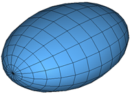
Figure 1. An ellipsoid of dimension (10, 7, 5)
The next example illustrates how a Parasolid geometry is represented in MotionSolve. The input CAD geometry for this example is shown below in Parasolid format along with the corresponding Post_Graphic model statement.
<Post_Graphic
    id                  = "900000"
    type                = "Parasolid"
    graphic_file        = "../gears.x_t"
    graphic_component   = "Gear1 Gear2"
    refinement_level    = "1"
    ref_marker_id       = "90000000"
/>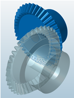
Figure 2. Parasolid graphic representing two bevel gears
Comments
- Not all graphic types are supported by the
Force_Contact modeling element. The graphic types that are
supported are:
- BoxDefinedFromCorner
- BoxDefinedFromCenter
- Cylinder
- Frustum
- Ellipsoid
- Sphere
- Plane
- TriaMesh
- UserGra
The remaining graphic types are used for visualization only.
- The BoxDefinedFromCenter and BoxDefinedFromCorner graphic types
are illustrated in the figure below.
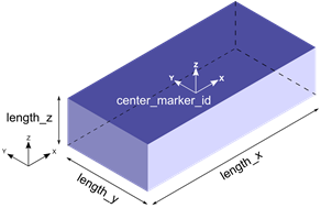
Figure 3. BoxDefinedFromCenter graphic type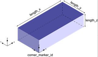
Figure 4. BoxDefinedFromCorner graphic typeBoth the BoxDefinedFromCenter and BoxDefinedFromCorner graphics are defined by their x, y, z lengths and a marker at the center or the corner, respectively.
- The Cylinder and Frustum graphic types are illustrated in the
figure below.
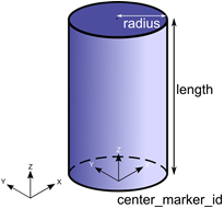
Figure 5. Cylinder graphic type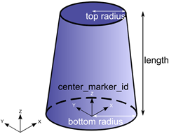
Figure 6. Frustum graphic typeThe Cylinder and Frustum graphics are defined by the radius (top and bottom in case of Frustum), length and the marker at the center of the geometry.
The TOP end of these graphics is the end that lies toward the negative Z axis, whereas the BOTTOM end is the one that lies toward the positive Z axis. These graphics may be defined with both, either TOP or BOTTOM, or neither ends capped. This is determined by the attribute ends_type:- ends_type = "OPEN" implies that neither ends of the Cylinder or Frustum is closed
- ends_type = "CLOSED" implies that both ends of the Cylinder or Frustum is closed
- ends_type = "TOP_ONLY" implies that only the TOP end of the Cylinder or Frustum is open
- ends_type = "BOTTOM_ONLY" implies
that only the BOTTOM end of the Cylinder or Frustum is openNote: If you would like to use the Cylinder or Frustum graphic in your mesh based contact model, make sure that ends_type is set to CLOSED so that the Cylinder or Frustum graphic is closed. Closed geometry is a requirement for the mesh based contact in MotionSolve. For more details, see Best Practices for Modeling 3D Contact Models in MotionSolve in the MotionSolve User's Guide.
- The Ellipsoid and Sphere graphic types are illustrated in the figure
below.
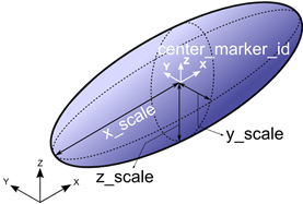
Figure 7. Ellipsoid graphic type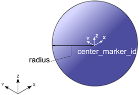
Figure 8. Sphere graphic typeThe Ellipsoid and Sphere graphic type are defined by the radii (x, y and z for Ellipsoid and a single radius for the Sphere) and the marker located at the center of the geometry.
- The Plane and SPDP graphic types are illustrated in the figure below.
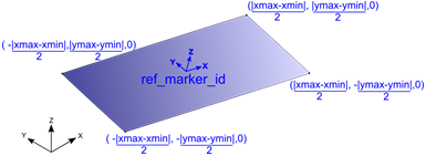
Figure 9. Plane graphic type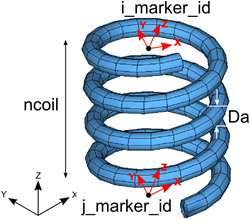
Figure 10. SPDP graphic typeThe Plane graphic type is defined by the spatial extent (xmin, xmax, ymin, ymax) and a marker. This marker is positioned at the center of the plane, and the Z axis of this marker determines the normal to the plane. The spatial lengths are defined in the coordinate system of the ref_marker_id(shown in blue above).
The SPDP graphic type is defined by the two attachment markers for the I and J body, the number of coils in the spring and the diameter of the coil.
- The CircleFromRM and CircleFromRadius graphic types are
illustrated in the figure below.
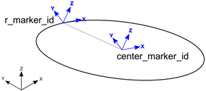
Figure 11. CircleFromRM graphic type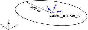
Figure 12. CircleFromRadius graphic typeThe CircleFromRM graphic type is defined by two markers. The origin of the circle is centered at the origin of the marker specified by center_marker_id; also the Z axis of this marker determines the normal to the plane of the circle. The origin of the r_marker_id is used to determine the radius of the circle as , where is the position of the center_marker_id and is the position of the r_marker_id.
The CircleFromRadius graphic type is defined by a marker and the radius. The origin of the circle is centered at the origin of the marker specified by center_marker_id; also the Z axis of this marker determines the normal to the plane of the circle. The radius is specified by the radius attribute.
For visualizing both these graphics, the circle is drawn using a number of straight line segments connected together. The attribute nseg defines the number of segments that should be used to draw the circle. A larger value will result in a smoother looking graphic.
- The ArcFromRM and ArcFromRadius graphic are illustrated in the
figure below.
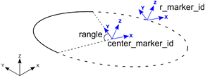
Figure 13. ArcFromRM graphic type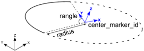
Figure 14. ArcFromRadius graphic typeThe ArcFromRM graphic type is defined by two markers. The origin of the arc is set to the origin of the marker specified by center_marker_id; also the Z axis of this marker determines the normal to the plane of the circle. The origin of the r_marker_id is used to determine the radius of the circle as , where is the position of the center_marker_id and is the position of the r_marker_id. The arc is drawn starting from the Y axis of the center_marker_id, in a counter clockwise fashion for the included angle, specified by rangle.
The ArcFromRadius graphic type is defined by a marker and the radius. The origin of the arc is set to the origin of the marker specified by center_marker_id; also the Z axis of this marker determines the normal to the plane of the circle. The radius is specified by the radius attribute. The arc is drawn starting from the Y axis of the center_marker_id,in a counter clockwise fashion for the included angle, specified by rangle.
For visualizing both these graphics, the arc is drawn using a number of straight line segments connected together. The attribute nseg defines the number of segments that should be used to draw the arc. A larger value will result in a smoother looking graphic.
- The LineFromMesh and Point graphic types are illustrated in the
figure below.
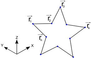
Figure 15. LineMesh graphic type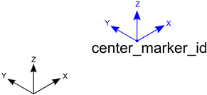
Figure 16. Point graphic typeThe LineFromMesh graphic type connects a number of vertices with straight lines. The number of lines to be drawn is specified by the num_line attribute. The X, Y and Z positions of the vertices are specified in the order in which the lines are to be drawn. For the above example, the vertices are specified in the following order:
(1) The order above specifies a line to be drawn between r1 and r2, r2 and r3, and so on.
The Point graphic type is defined as the point that is specified by the origin of the center_marker_id.
- The LineFromMesh and Point graphic types are illustrated in the
figure below.
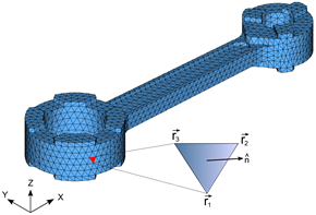
Figure 17. TriaMesh graphic type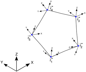
Figure 18. Outline graphic typeThe TriaMesh graphic is defined as a collection of triangle elements that usually share vertices and edges between them. This type of mesh is commonly used for representing CAD geometry in analysis. The triangles, by themselves are 2D. When connected together, these triangles can represent a 3D surface. The surface may or may not have free edges. Further, there is no requirement that the mesh defines a contiguous solid. In other words, all parts of the mesh need not be connected.
The surface normal at each triangle is defined as the cross product of the edges such that the normal points outward when the vertices are specified in a counter-clockwise manner. In the figure above, the normal is defined as
.
The Outline graphic is defined by a list of marker IDs. A poly line is drawn through the origins of each of these markers. The number of markers is specified by the attribute num_marker_id.
- The ParamCurve and DeformCurve graphic types are illustrated
in the figure below.
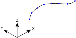
Figure 19. ParamCurve graphic type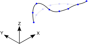
Figure 20. DeformCurve graphic typeThe ParamCurve graphic type is used to represent a curve defined in the model as a Reference_ParamCurve element. The graphic is defined by a number of straight line segments connecting vertices on the curve defined by curve_id.
The DeformCurve graphic type is used to represent a deformable curve defined in the model as a Reference_DeformCurve element. The graphic is defined by a number of straight line segments connecting vertices on the curve defined by curve_id. Since this graphic represents a deformable curve, the graphic deforms along with the curve as the simulation progresses.
The attribute nseg defines the number of segments that should be used to draw the curves. A larger value will result in a smoother looking curve. Depending on how the points are defined, the ParamCurve or DeformCurve graphic can be open or closed.
- The ParamSurface and DeformSurface graphic types are
illustrated in the figure below.
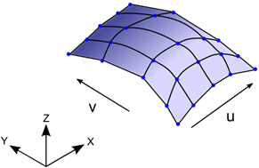
Figure 21. ParamSurface graphic type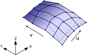
Figure 22. DeformSurface graphic typeThe ParamSurface graphic type is used to represent a surface defined in the model as a Reference_ParamSurface element. The graphic is defined by a number of straight line segments connecting vertices on the surface defined by surface_id.
The DeformSurface graphic type is used to represent a deformable surface defined in the model as a Reference_DeformSurface element. The graphic is defined by a number of straight line segments connecting vertices on the surface defined by surface_id. Since this graphic represents a deformable surface, the graphic deforms along with the surface as the simulation progresses.
The attribute nseg_u and nseg_v defines the number of segments that should be used to draw the curves along the U and V directions of the surface respectively. Larger values will result in a smoother looking surface.
- The Parasolid graphic type allows you to use Parasolid
geometry as a graphic in MotionSolve. The graphic is
defined by the name and location of the Parasolid graphic file and the name(s)
of the parts in the Parasolid assembly.
To import Parasolid geometry into your model, you must use Import CAD or FE from the Tools menu in MotionView. Please see tutorial MV-1035 for more information.
After the simulation is complete, MotionSolve tessellates the Parasolid geometry and writes it to the animation H3D file for visualization.
- The UserGra graphic type allows you to define your own
graphic. This can be done by defining your own subroutine or script. You can create
vertices and triangles using the access functions ADD_GRA_NODE,
SET_GRA_NODE and ADD_GRA_TRIA provided by
MotionSolve. These access functions allow you to
create a triangular mesh that can be then used as a graphic in your model. For more
information and examples, please refer to the documentation on GRASUB.
Using a GRASUB is particularly useful when you would like to redraw your graphic as the simulation progresses.
- If you want to use CAD geometry (for example IGES, STP, and
so on) for contact modeling, then the native CAD format needs to be converted to
Triamesh elements. This can be done in two ways:
- Import the CAD model into HyperMesh, mesh it, and export the H3D file. Import this H3D file into MotionView and define contact.
- From within MotionView, select Import CAD or FE from the Tools menu in MotionView. This utility uses HyperMesh to perform the translation. It is intended for those who are not familiar with HyperMesh.
- All graphic entities are written to the animation H3D file so the system behavior can be visualized in HyperView.
- All primitive 3D graphics (Sphere, Ellipsoid, Cylinder,
Frustum, BoxDefinedFromCorner and BoxDefinedFromCenter) are converted to a
triangular meshed representation when they are written to the animation H3D
file.
The density of their mesh can be controlled by the parameter refinement_level. A higher value ofrefinement_level increases the mesh density by adding more and more triangles.
A higher mesh density tends to produce more accurate contact forces, however adding more triangles usually increases the simulation time.
The following figures show the effect of increasing refinement level on some of the primitive 3D shapes.
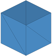
Figure 23. Box with refinement_level = 0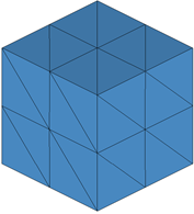
Figure 24. Box with refinement_level = 1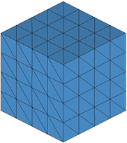
Figure 25. Box with refinement_level = 2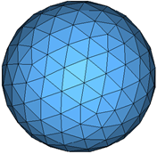
Figure 26. Sphere with refinement_level= 2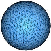
Figure 27. Sphere with refinement_level = 3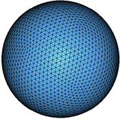
Figure 28. Sphere with refinement_level = 4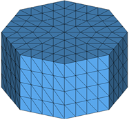
Figure 29. Cylinder with refinement_level = 1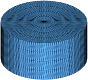
Figure 30. Cylinder with refinement_level = 2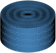
Figure 31. Cylinder with refinement_level = 3The refinement_level attribute may also be used for a TriaMesh graphic type. Increasing the refinement level by 1 results in each triangle being divided into 4 triangles as illustrated in the figures below. Note: if you wish to use your TriaMesh graphic as is, set this attribute to 0 or do not define it.
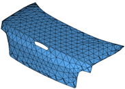
Figure 32. Triamesh with refinement_level = 0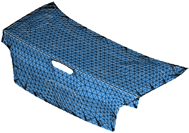
Figure 33. Triamesh with refinement_level = 1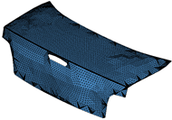
Figure 34. Triamesh with refinement_level = 2The refinement_level is supported for the following graphic types:- BoxDefinedFromCenter
- BoxDefinedFromCorner
- Sphere
- Ellipsoid
- Cylinder
- Frustum
- Plane
- TriaMesh
- Parasolid
- For contact, MotionSolve tries to use analytical representations for all primitive 3D graphics (Sphere, Ellipsoid, Cylinder, Frustum, BoxDefinedFromCorner, and BoxDefinedFromCenter) when possible, to compute accurate, fast, and smooth contact forces. See Force: Contact for more information.