hexa nugget
Use the hexa nugget realization to create hexa clusters between shell components.
Contacts are defined between the shell components and the appropriate hexa nodes. A heat affected zone for the shells from ultra-high strength steel material is also created.
Hexa Nugget realizations can be used for any amount of parallel combinations of shell components.
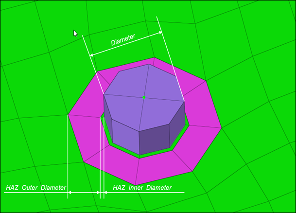
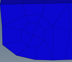
Figure 1. HAZ Dimensions
General Info
| Parameter | Action |
|---|---|
| Tolerance | Specify a distance from the connector location. Only the entities within this tolerance can be taken into account for the final realization. The tolerance is used to verify whether adequate link candidates are available to be connected with respect to the number of layers. |
Weld Shape
| Parameter | Action |
|---|---|
| Hexa Number | Create a hexa cluster of 4 hexas, arranged in a predefined
pattern. Note: By default, Hexa Number is set to 4 hexa. You
cannot edit this field.
|
| Coats | Specify the number of hexa elements required along the
thickness. Note: By default, Hexa Coats is set to 1 for a
hexa nugget connector. You cannot edit this
field.
|
Realization Details
| Parameter | Action |
|---|---|
| Diameter Option | Choose how the diameter is defined. This field is used for
realizations based on hexa elements, where the size of the
realized element (hexa) is created based on the diameter value.
|
| Hexa Thickness Option | Project the hexa spot to touch the shell elements. The
position is independent from any thickness. Note: By default,
Hexa Thickness Option is set to shell gap. You cannot edit
this field.
|
Connectivity Info
| Parameter | Option |
|---|---|
| Connectivity |
Note: By default, Connectivity is set to contact, but you can
also choose imprint.
|
| HAZ | Create the quad weld elements and stitch them to both links by adjusting their mesh. Perform all required HAZ. |
| Enable Condition HAZ | Control which parts need to receive heat affected zones during the realization. |
| Skip Imprint | Create the quad weld elements, but do not change the meshes
of the links. Instead, create additional elements to represent the requested HAZ. These elements are organized in the ^conn_imprint component. You can use these elements
for a later manual imprint after they have been manipulated
to your need. This can be helpful in more complex areas,
where the standard imprint functionality fails, for example,
when working with conflicting connectors.
Note: The quad
weld elements are not attached to the links. The
connection needs further attention.
|
Contact Info
| Parameter | Action |
|---|---|
| Contact Creation Option | Choose a method for creating contacts.
|
Auto Correction
| Parameter | Option |
|---|---|
| Allow Reposition | Reposition hexa elements and HAZ elements. If the option is deselected, the connector will fail when the connector is too close to free or feature edges where the nugget and HAZ elements cannot be accommodated. |
| Reposition Tolerance | Specify a maximum allowable distance by which hexa elements and HAZ elements are repositioned based on connector location to edge. |
| Control Distance |
Choose a method for controlling distance.
|
| Requested Distance | Choose whether the distance to reposition is based on minimum distance to imprint or a minimum distance to connector projection. |
| Distance | Choose whether to manually specify a distance or use the minimum element size from the element criteria file. |
HAZ Info
| Parameter | Option |
|---|---|
| HAZ Material Condition | Enable the selection of UHSS material which controls which parts need to receive heat affected zones during the realization. |
| UHSS Material Option | Choose a method for selecting UHSS material.
|
| HAZ Dimension Scheme | Choose a setting for defining HAZ diameters. |
| HAZ Inner Diameter |
|
| HAZ Outer Diameter |
|
| HAZ Layer 2 | Enables you to specify the HAZ Outer Diameter 2. By default, this checkbox is cleared and the HAZ Outer Diameter 2 cannot be defined. |
| HAZ Outer Diameter 2 |
Note: For values and scale factors, this value must be greater
than the value used for defining the HAZ Outer
Diameter.
|
Property and Material Info
| Parameter | Option |
|---|---|
| HAZ Material Option | Choose a method for assigning material for the HAZ.
|
| HAZ Property Option | Choose a method for assigning a property to HAZ.
|
| Nugget Material Option | Choose a method for creating and assigning material to nuggets.
|
| Itemize Multilayer Connections | Itemize a multilayer connection. For example, in the case of
a three layer connection, the two hexa clusters will be handled
separately and will be assigned two different materials. At the
same time, a two layer connection between the same two links
will be assigned another material. Names are created as following:
Note: Only available when Nugget Material Option is set
to Create one material per each link
combination.
|
| Select Nugget Property | Select a property from the current model. |
Behavior
| Parameter | Option |
|---|---|
| Non-normal | Attempt to realize connectors if the shell layers are not normal to each other. |
| Project Hexa Faces To Shell | Investigate and project each individual node, enabling you to
expect and accept penetrations. In some border cases, during realization not all nodes of the appropriate hexa(cluster)-side are positioned exactly on the shell. This is due to some simplifications during the projection routine because it is estimated that the shells will not be too curvy and will be pretty plain. Therefore, not every node is individually investigated and projected to the same plane as the first one. |
| Ensure Hexa Projection | When enabled, all hexa node projections to a link that are
beyond the specified tolerance (0.01*diameter) are marked as an
error. Tip: Enable this checkbox when working
with connections that use a contact
definition.
|
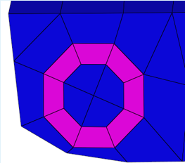
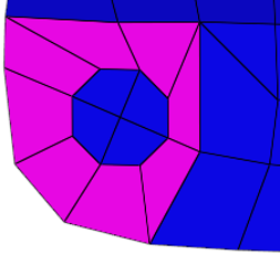
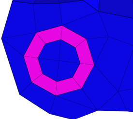
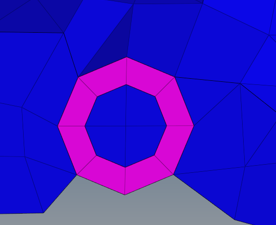
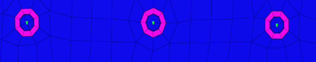
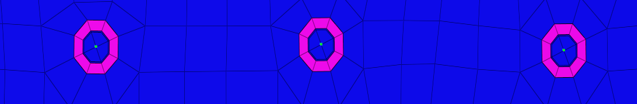
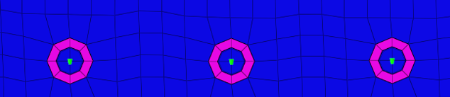
| Preserve Washer | Choose a method for preserving washers during the
realization. Initial situation with perfectly meshed
washers. Figure 2. Original  Figure 3. No Washer Preservation  Figure 4. Preserve Washer, Allow Remesh  Figure 5. Preserve Washer, No Remesh |
| Feature Angle | Specify a value used to determine important features, which
need to be kept when doing the imprint. Note: Features crossing
the HAZ and close by cannot be kept.
|
| Nugget Narrow Case | Choose a method to control the edge treatment, and HAZ
element snapping to edge, if the connector is close to the edge.
|
| Nugget Orientation | Choose a method for orienting hexa nuggets during the realization.
|
| Post Collector Name Setting | While realizing a hexa nugget connector, choose to name the collectors created after the realization with link names or link IDs. |
| Post Collector Name Separator | Choose a separator to use between collector names. |
| Unrealize Remesh or Rebuild | Remeshes or rebuilds HAZ elements and the elements
surrounding it upon connector unrealization. Option is available
only when unrealize remesh or rebuild is set to Remesh or
Rebuild. Number of layers to be considered around HAZ elements
for remesh or rebuild can be controlled with user input value
for the layers.
|