BT Card
This card defines a mesh of surface triangles in the shape of a flat triangle.
On the Construct tab, in the Surfaces group,
click the ![]() Triangle (BT) icon.
Triangle (BT) icon.
Note: For creating planar surface meshes, in general the PM card would be preferred over the
BT card.
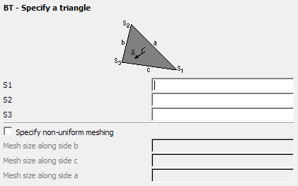
Figure 1. The BT - Specify a triangle dialog.
Parameters:
- S1, S2, S3
- The points S1 to S3 are the three corner points of the triangle. These points should have been defined previously with the DP card.
- Specify non-uniform meshing
- Usually a triangle is meshed according to the edge length specified with the IP card. It may be required to use a finer mesh size in a particular direction. Check this item if finer meshing is required along any edge. The mesh sizes are in metres and are scaled by the SF card.
- Mesh size along side b:
- The mesh size along edge S2–S3.
- Mesh size along side c:
- The mesh size along edge S3–S1.
- Mesh size along side a:
- The mesh size along edge S1–S2.
Examples of BT card usage
The mesh shown below was created with a BT card using uniform meshing.

Figure 2. Example of a uniform mesh in the shape of a triangle created with the BT card.

Figure 3. Example of a non-uniform mesh in the shape of a triangle created with the BT card.