ME Card
This card must be used to distinguish the different media and to create segments and triangles (metallic or dielectric) within or on the surface of dielectrics solved with FEM or VEP as well as MoM/MLFMM.
In the Home tab, in the Define group, click
the ![]() Media icon. From
the drop-down list select the
Media icon. From
the drop-down list select the ![]() Set medium (ME) icon.
Set medium (ME) icon.
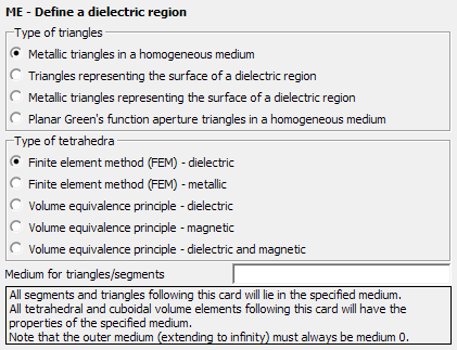
Figure 1. The ME - Define a dielectric region dialog.
Parameters:
- Metallic triangles in a homogeneous medium
- If this option is selected all the surface structures between this card and the next ME card are assumed to be fully contained inside the medium specified in Medium for triangles/segments.
- Triangles representing the surface of a dielectric region
- If this option is selected all the surface structures created between this card and
the next ME card are assumed to define the boundary between two media. Note that the
user needs to provide the names of the media on both sides of the triangles. The normal
vector points from Medium A to Medium B.
For example consider a dielectric body of medium, DIELECTRIC constructed so that all
the triangle normals point outward. Then Medium A is to be set to
DIELECTRIC and Medium B to 0 (the number zero always represents
the outer free space region).Note: The dialog layout changes according to the selected options. For example the Medium A and Medium B text boxes are visible only when selecting the 2nd or 3rd options in the Type of triangles group.
- Metallic triangles representing the surface of a dielectric region
- If this option is selected all the surface structures created between this card and the next ME card are assumed to define a metallic boundary between two media. The selection of the sides is the same as for the non-metallic case, Triangles representing the surface of a dielectric region.
- Planar Green’s function aperture triangles in a homogeneous medium
- All triangles generated after this card are planar Green’s function aperture triangles in a homogeneous medium.
- Finite element method (FEM) - dielectric
- If this option is selected dielectric tetrahedral mesh elements will be solved with the FEM.
- Finite element method (FEM) - metallic
- If this option is selected metallic tetrahedral mesh elements are considered as part of the FEM solution. The medium label “Perfect electric conductor FEM” should be used to specify PEC metallic tetrahedra.
- Volume equivalence principle - dielectric
- If this option is selected dielectric tetrahedral mesh elements will be solved with the VEP.
- Volume equivalence principle - magnetic
- If this option is selected magnetic tetrahedral mesh elements will be solved with the VEP.
- Volume equivalence principle - dielectric and magnetic
- If this option is selected dielectric and magnetic mesh elements will be solved with the VEP.
All the wire segments that follow this card are assigned the properties of the medium in which they are located. Triangles are treated according to whether they are metallic triangles or triangles on the boundary of a dielectric object. Here the properties of the media are assigned to the respective sides.
All triangles and segments before an ME card represent metallic structures in free space. This is also the case when an input file does not have an ME card.
When using the FEM and meshing structures into tetrahedral elements or when using the VEP in connection with the MoM/MLFMM and meshing into cuboidal volume elements, then the selection in the Type of triangles group is not relevant. The specified medium will be used (Medium A if there are multiple media input fields).
- Metallic triangles in free space (Medium 0) on the bottom and side of the cylinder
- Metallic triangles also forming the border surface of the dielectric body on the lid of the cylinder (which is also the base of the dielectric cone)
- Dielectric triangles forming the surface of the dielectric body (the boundary between Medium 1 — the inner dielectric region — and Medium 0 — the free space outer region) on the top surface of the cone

Figure 2. Example of a dielectric cone on top of a metallic cylinder to created with the ME card.