WG Card
The WG card is used to create a wire grid in the shape of a parallelogram.
On the Construct tab, in the Wires group,
click the ![]() Wire grid (WG) icon.
Wire grid (WG) icon.
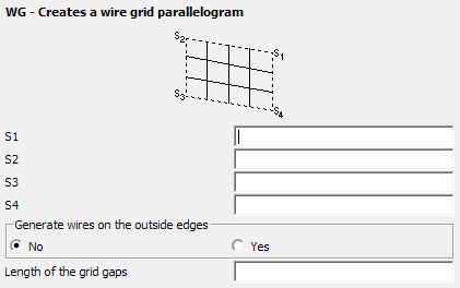
Figure 1. The WG - Creates a wire grid parallelogram dialog.
Parameters:
- S1, S2, S3, S4
- The four corners of the parallelogram in consecutive order.
- Generate wires on the outside edges
- Select No to create the wires inside the parallelogram only or Yes to generate all wires. This option is important when creating two adjacent parallelograms to ensure that the segments along the sides are not generated twice.
- Length of the grid gaps
- The maximum segment length is given by the IP card. This parameter is an integer number and specifies the density of the grid. If, for example, this is set to 2, the wires only cross at every second segment.
Examples of WG Card Usage
The following wire grids are created using the WG card. The grid spacing is specified in terms of the number of segment lengths as defined with an IP card.
Figure 2. Examples of wire grids created with the WG card . The example on the right has a value of 2 in Length of the grid gaps.