FO Card
The FO card is used to define an area in which the surface current density is an approximation.
On the Solve/Run tab, in the Rays group,
click the ![]() Physical optics
icon. From the drop-down list, select the
Physical optics
icon. From the drop-down list, select the ![]() Fock current (FO) icon.
Fock current (FO) icon.
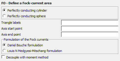
Figure 1. The FO - Define a Fock-current area dialog.
Parameters:
- Perfectly conducting cylinder
- Select this option if the Fock area is/ resembles a cylinder.
- Perfectly conducting sphere
- Select this option if the Fock area is/resembles a sphere.
- Triangle labels
- The label of the metallic triangles that form the surface of the Fock area (for example, the surface of the cylinder).
- Axis start point
- This dialog is only visible for Fock cylinders and correspond to the start of the cylinder axis.
- Axis end point
- This dialog is only visible for Fock cylinders and correspond to the end of the cylinder axis.
- Sphere centre point
- This dialog is only visible for Fock spheres and should correspond to the centre of the sphere.
- Formulation of the Fock currents
- The type of process for the Fock currents, either the Daniel Bouche method or the Louis N. Medgyesi–Mitschang method.
- Decouple with moment method
- Select this check box to force Feko to neglect the coupling between the MoM and Fock regions, so that there is no feedback by which the Fock currents may influence the current distribution in the MoM region. This option, which is particularly applicable when the MoM and Fock regions are not in close proximity, should result in a considerable reduction in computational effort and storage space.
The radius of the cylinder or sphere does not have to be defined. It is determined by the distance to the metallic triangles, with the label specified in Triangle labels.
The cylinder Fock currents can also be applied to cones (KK card, approximated by a staircase construction of cylinders) and sections of a torus that resembles a cylinder (TO card). Although the FO card is strictly only applicable to spherical and cylindrical surfaces, it is often a good approximation on conical and toroidal surfaces.
It must be noted that the search for creeping rays on the Fock surface does not take into account multiple Fock regions, for example, one creeping ray can only exist in one Fock region. Therefore, when for instance modelling a sphere and using symmetry, it is highly advisable to create part of the sphere, then use the SY card to mirror it, and only then use one FO card which applies to the whole sphere. When using SY or TG cards, they do operate on already existing Fock regions defined above these cards and thus mirror or move them, but with the SY card the problem is that after applying symmetry there exist multiple Fock regions. The creeping rays along geodesic lines stop at the boundary of each Fock region.