Aerodynamic Forces
Basic Approach
The following is an aerodynamics concept as proposed by Manfred Mitschke and Henning Wallentowitz 1.
The resultant aerodynamic force and torque is considered to act on a reference point Oc placed on the road surface at the center of the four wheels.
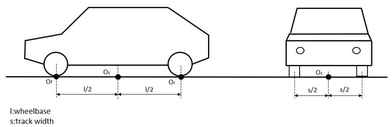
Figure 1.
Fa,x = cx(τL)*P(vr)
Fa,y = cy(τL)*P(vr)
Fa,z = cz(τL)*P(vr)
Ma,x = cmx(τL)*l*P(vr)
Ma,y = cmy(τL)* l*P(vr)
Ma,z = cmz(τL)* l*P(vr)
Where ci express the aerodynamic coefficients, τL the relative airflow incidence angle, vr the resulting velocity, P the dynamic pressure and l the wheelbase.
The coordinate system in which the above defined force and torque components are to be applied is located in Oc and fixed to the car body.
On Velocities
A diagonal airflow results in a flow velocity vr with an incidence angle τL to the vehicle’s longitudinal axis. Both parameters vr and τL can be calculated by vector addition of the road speed vector v (negative car speed vector) and the wind velocity vector vw.
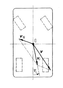
Figure 2.
On P(vr)
The dynamic pressure can be calculated using the air density ρ, the resulting velocity vr, and the following formula.
P(vr) = 0.5 * ρ * vr2
The air density is dependent on the ambient temperature and pressure of the environment, and the ideal gas constant for air, often regarded as constant.
Vertical Force and Pitch Torque
The vertical force Fa,z and the pitch torque Ma,y are replaced by two vertical forces acting at the center points of the suspensions Of and Or at ground level introducing cz,f and cz,r.
Fa,zf = cz,f(τL)*P(vr)
Fa,zr = cz,r(τL)*P(vr)- Summary of aerodynamic forces and moments formulas
-
Fa,x = 0.5*cx(τL)* ρ * A* vr2
Fa,y = 0.5*cy(τL)* ρ * A* vr2
Fa,zf = 0.5*cz,f(τL)* ρ * A* vr2
Fa,zr = 0.5*cz,r(τL)* ρ * A* vr2
Ma,x = cmx(τL)* l* ρ * A* vr2
Ma,z = cmz(τL)* l* ρ * A* vr2
Where A is the frontal area of the car. Vehicle frontal areas are typically in the range of 1.5 m2 < A < 2.5 m2 for passenger cars and 4 m2 < A < 9 m2 for trucks and buses.
How to Determine ci
As a very rough approximation the ci can be regarded as constants, and to disable aerodynamic totally, all ci can be set to zero.
| τL =0deg | τL =10deg | τL =20deg | τL =30deg | |
|---|---|---|---|---|
| cx | 0.3 | 0.31 | 0.32 | 0.33 |
| cy | 0 | 0.4 | 0.8 | 1.2 |
| cz,f | 0.1 | 0.2 | 0.3 | 0.4 |
| cz,r | 0 | 0.1 | 0.2 | 0.3 |
| cmx | 0 | 0.03 | 0.06 | 0.09 |
| cmz | 0 | 0.04 | 0.08 | 0.12 |
A limitation of using this table is not allowing situations where the car is subjected to diagonal airflow of over 30 degrees. Such conditions, especially pure sidewind conditions, will be considered for implementation in future releases.
ci coefficients could be derived by a virtual wind tunnel experiment. The values measured in such an experiment would be the constrained forces at Oc, Or and Of as functions or vr and τ.
Property File
Aerodynamic system uses aerodynamic property file (.aae) to provide access to all the parameters to the solver. The reference to the .aae file is sent to the solver as a Solver String in the sa_aero_params solver array.
- TiemOrbit Format
- The TeimOrbit reader can parse various entities to get data from the aerodynamic
property file. These entities include: attributes, blocks, sub-blocks, tables, units,
and comments.
- Attributes
- Attributes form the smallest data member of the driver file. Attributes can be
real, integer, strings or Booleans (True/False).
[BLOCK_NAME]
ATTRIBUTE_1  = 'TRUE'
ATTRIBUTE_2  = 1.0
ATTRIBUTE_3  = 'Wind_velocity'
ATTRIBUTE_4  = 8
Attribute names are:- Strings
- Case insensitive, for example: TAG and tag are equivalent.
- In the above example, the attributes are: TAG, SATURATION, LOOK_AHEAD_TIME, DEMAND_FILE, INTEGRATION_STEP_SIZE are the attribute names.
Attribute value:- Real, integer, string, bool
- Strings should be written in ‘single quotes’ or “double quotes”
- 0, 0.00, N, NO, FALSE, F are all depicted as false
- 1, 1.00, T, TRUE, Y, YES are all depicted as true
- Case sensitive
Format:ATTRIBUTE_NAME = ATTRIBUTE_VALUE - Block
- Blocks form the most versatile data structure of the reader utility. It acts
as container for all other data members except a block.
- Block can contain any number of sub-blocks.
- Block cannot contain a block.
- Block can contain multiple tables but only storing them in different sub-blocks.
Format:[BLOCK_NAME] ATTRIBUTE(s) SUBBLOCK(s) TABLEBlock ends with the end of file or start of new Block.
- Sub-block
- Sub-blocks are structurally similar to blocks with an only difference that
they cannot contain sub blocks or blocks.
- A sub block cannot contain more than one table.
Format:(SUBBLOCK_NAME) ATTRIBUTE(s) TABLE(s) - Table
-
Data structure which consists of fields (rows and columns).
- Table can contain any type of attributes.
- In no label is provided, the default is to label them as indices starting from 0.
Format:{LABEL1 LABEL2 LABEL3} ATTRIBUTE00 ATTRIBUTE01 ATTRIBUTE02 ATTRIBUTE10 ATTRIBUTE11 ATTRIBUTE12 ATTRIBUTE20 ATTRIBUTE21 ATTRIBUTE22 - Units
-
‘Units’ is a special block that conveys the reader units of the property file.
- Every property sheet should necessarily have a units block.
- User defined units in tables.
- Comment
- Anything written in line after ‘$’ is ignored by the reader
utility.
[ENVIRONMENT]
$These are environment conditions for the simulation
GAS_CONSTANT                    	= 287e3
AMBIENT_PRESSURE                	= 0.101325
AMBIENT_TEMPERATURE             	= 298
WIND_VELOCITY		= 'WIND_VELOCITY'
- Altair Header
- The Altair header block provides the basic information of the property file to the
solver.
$-----------------------------------------------------------------ALTAIR_HEADER
[ALTAIR_HEADER]
FILE_TYPE 	= 'AAE'
FILE_VERSION 	= 1.0
FILE_FORMAT 	= 'ASCII'
ENTITY_TYPE     	= 'AERODYNAMIC_FORCE'
Type Requirement Block name
[ALTAIR_HEADER]String REQUIRED FILE_TYPE Attr-String REQUIRED - Read and extract information
- Multiple file format support
FILE_VERSION Attr-Real REQUIRED FILE_FORMAT
‘ASCII’Attr-String OPTIONAL
Optional currently, required for future enhancement.ENTITY_TYPE
'AERODYNAMIC_FORCE'Attr-String OPTIONAL
Provides info on the entity associated with the property file. - Units
- Solver parses the AAE in MotionSolve during the simulation to extract aerodynamic
and environment data. While parsing the property file, solver reads the units block to
convert data in the property file to SI units and use them further in the
simulation.Units block specifies the units of all the data mentioned in the property file. The units are specified for length, force, angle, mass, time and temperature.
- Units are not case sensitive – meter, Meter, METER, or MeTer are all interpreted as same.
- Units block is require for all types of data files.
$--------------------------------------------------------------------------UNITS
[UNITS]
(BASE)
{length  force      angle       mass    time    temperature}
'mm'   'newton'   'degrees'   'kg'    'sec'     'kelvin'
Dimension Options Conversion Factor to SI Length meter or meters or m
foot or feet or ft
mile or miles
millimeter or millimeters or mm
inch or inches or in1.0
0.3048
1609.344
0.001
0.0254Force Newton
Dyne
KNewton
Ounce_Force
Kilogram_Force or Kgf
KPound_Force
Pound_Force or lbf
1.0
0.00001
1000
0.27801
9.80665
4448.2216
4.4482216Angle Radian or radians or rad or r
Degrees or degree or deg or d1.00
0.017453Mass Kg or kilogram or kilograms
G or gram or grams
Pound or pounds or lb or lbs1.0
0.001
0.453592Time sec or second or seconds
milliseconds or millisecond or millisec or millisecs or ms1.0
0.001Temperature Kelvin or k
Note: More temperature units will be supported in upcoming versions.1.0 - Geometric properties
- This section contains the data related to vehicle geometry. Calculation of the
aerodynamic forces require the frontal area of the vehicle which is specified in this
block.
$---------------------------------------------------------------GEOMETRIC_PROPERTIES
[GEOMETRIC_PROPERTIES]
FRONTAL_SECTION_AREA        = 2e6
Block name
[GEOMETRIC_PROPERTIES]String REQUIRED FRONTAL_SECTION_AREA Attr-Real REQUIRED
Frontal area of the vehicle.
Unit – L2 - Environment
- This section contains the data related to the environment. Calculation of the
aerodynamic forces require the ambient pressure, ambient temperature and wind velocity
which is specified in this
block.
$---------------------------------------------------------------ENVIRONMENT
[ENVIRONMENT]
GAS_CONSTANT                    	= 287e3
AMBIENT_PRESSURE                	= 0.101325
AMBIENT_TEMPERATURE             	= 298
WIND_VELOCITY		= 'WIND_VEL_1'
$Wind vel is with respect to global frame
$---------------------------------------------------------------WIND_VELOCITY
[WIND_VEL_1]
$Wind vel is with respect to global frame
VX                    = 1000
VY                    = 0
VZ                    = 0
Type Requirement Block name
[ENVIRONMENT]String REQUIRED GAS_CONSTANT Attr-Real REQUIRED
Unit – FLM-1Temp-1AMBIENT_PRESSURE Attr-Real REQUIRED
Unit – FL-2AMBIENT_TEMPERATURE Attr-Real REQUIRED
Unit – TempWIND_VELOCITY
REQUIRED
Unit – LT-1 - Drag Coefficient
- This section contains the table of drag coefficients with respect to different
incidence angles. The table is provided as a spline as shown in the block and the
interpolation scheme is
provided.
$---------------------------------------------------------------DRAG_COEFFICIENT
[DRAG_COEFFICIENT]
INTERPOLATION = 'AKIMA'
(SPLINE_DATA)
{INCIDENCE_ANGLE    COEFFICIENT}
0.0                 0.3
10.0                0.31
20.0                0.32
30.0                0.33
Type Requirement Block name
[DRAG_COEFFICIENT]String REQUIRED INTERPOLATION Attr-String OPTIONAL
If absent:- Interpolation scheme = AKIMA
If present:- Interpolation scheme = INTERPOLATION.value.
- Options - AKIMA, CUBIC, LINEAR, QUINTIC.
These interpolation schemes are similar to those of Altair MotionSolve. See the Altair MotionSolve documentation for details on interpolation schemes.
SPLINE_DATA Attr-Table
INCIDENCE_ANGLE vs COEFFICIENTREQUIRED
Drag coefficient values at different values of incidence angles
- Side Force Coefficient
- This section contains the table of sideforce coefficients with respect to different
incidence angles. The table is provided as a spline as shown in the block and the
interpolation scheme is
provided.
$--------------------------------------------------------------- SIDEFORCE_COEFFICIENT
[SIDEFORCE_COEFFICIENT]
INTERPOLATION = 'AKIMA'
(SPLINE_DATA)
{INCIDENCE_ANGLE    COEFFICIENT}
0.0                 0.3
10.0                0.31
20.0                0.32
30.0                0.33
Type Requirement Block name
[SIDEFORCE_COEFFICIENT]String REQUIRED INTERPOLATION Attr-String OPTIONAL
If absent:- Interpolation scheme = AKIMA
If present:- Interpolation scheme = INTERPOLATION.value.
- Options - AKIMA, CUBIC, LINEAR, QUINTIC.
These interpolation schemes are similar to those of Altair MotionSolve. See the Altair MotionSolve documentation for details on interpolation schemes.
SPLINE_DATA Attr-Table
INCIDENCE_ANGLE vs COEFFICIENTREQUIRED
Sideforce coefficient values at different values of incidence angles
- Front Lift Coefficient
- This section contains the table of front lift coefficients with respect to different
incidence angles. The table is provided as a spline as shown in the block and the
interpolation scheme is
provided.
$--------------------------------------------------------------- LIFT_COEFFICIENT_FRONT
[LIFT_COEFFICIENT_FRONT]
INTERPOLATION = 'AKIMA'
(SPLINE_DATA)
{INCIDENCE_ANGLE    COEFFICIENT}
0.0                 0.3
10.0                0.31
20.0                0.32
30.0                0.33
Type Requirement Block name [LIFT_COEFFICIENT_FRONT]
String REQUIRED INTERPOLATION Attr-String OPTIONAL
If absent:- Interpolation scheme = AKIMA
If present:- Interpolation scheme = INTERPOLATION.value.
- Options - AKIMA, CUBIC, LINEAR, QUINTIC.
These interpolation schemes are similar to those of Altair MotionSolve. See the Altair MotionSolve documentation for details on interpolation schemes.
SPLINE_DATA Attr-Table
INCIDENCE_ANGLE vs COEFFICIENTREQUIRED
Front lift coefficient values at different values of incidence angles
- Rear Lift Coefficient
- This section contains the table of rear lift coefficients with respect to different
incidence angles. The table is provided as a spline as shown in the block and the
interpolation scheme is
provided.
$--------------------------------------------------------------- LIFT_COEFFICIENT_REAR
[LIFT_COEFFICIENT_REAR]
INTERPOLATION = 'AKIMA'
(SPLINE_DATA)
{INCIDENCE_ANGLE    COEFFICIENT}
0.0                 0.3
10.0                0.31
20.0                0.32
30.0                0.33
Type Requirement Block name [LIFT_COEFFICIENT_REAR]
String REQUIRED INTERPOLATION Attr-String OPTIONAL
If absent:- Interpolation scheme = AKIMA
If present:- Interpolation scheme = INTERPOLATION.value.
- Options - AKIMA, CUBIC, LINEAR, QUINTIC.
These interpolation schemes are similar to those of Altair MotionSolve. See the Altair MotionSolve documentation for details on interpolation schemes.
SPLINE_DATA Attr-Table
INCIDENCE_ANGLE vs COEFFICIENTREQUIRED
Rear lift coefficient values at different values of incidence angles
- Roll Coefficient
- This section contains the table of roll coefficients with respect to different
incidence angles. The table is provided as a spline as shown in the block and the
interpolation scheme is
provided.
$--------------------------------------------------------------- ROLL_COEFFICIENT
[ROLL_COEFFICIENT]
INTERPOLATION = 'AKIMA'
(SPLINE_DATA)
{INCIDENCE_ANGLE    COEFFICIENT}
0.0                 0.3
10.0                0.31
20.0                0.32
30.0                0.33
Type Requirement Block name [ROLL_COEFFICIENT]
String REQUIRED INTERPOLATION Attr-String OPTIONAL
If absent:- Interpolation scheme = AKIMA
If present:- Interpolation scheme = INTERPOLATION.value.
- Options - AKIMA, CUBIC, LINEAR, QUINTIC.
These interpolation schemes are similar to those of Altair MotionSolve. See the Altair MotionSolve documentation for details on interpolation schemes.
SPLINE_DATA Attr-Table
INCIDENCE_ANGLE vs COEFFICIENTREQUIRED
Roll coefficient values at different values of incidence angles
- Yaw Coefficient
-
This section contains the data related to vehicle geometry. Calculation of the aerodynamic forces require the frontal area of the vehicle which is specified in this block.
$--------------------------------------------------------------- YAW_COEFFICIENT [YAW_COEFFICIENT]
INTERPOLATION = 'AKIMA'
(SPLINE_DATA)
{INCIDENCE_ANGLE    COEFFICIENT}
0.0                 0.3
10.0                0.31
20.0                0.32
30.0                0.33
Type Requirement Block name [YAW_COEFFICIENT]
String REQUIRED INTERPOLATION Attr-String OPTIONAL
If absent:- Interpolation scheme = AKIMA
If present:- Interpolation scheme = INTERPOLATION.value.
- Options - AKIMA, CUBIC, LINEAR, QUINTIC.
These interpolation schemes are similar to those of Altair MotionSolve. See the Altair MotionSolve documentation for details on interpolation schemes.
SPLINE_DATA Attr-Table
INCIDENCE_ANGLE vs COEFFICIENTREQUIRED
Yaw coefficient values at different values of incidence angles
Building a Vehicle Model with an Aerodyamic System
In Altair MotionView, models are assembled from libraries of pre-defined systems using the Assembly Wizard. The Assembly Wizard dialog guides you through the assembly process, ensuring that your selections are compatible.
- Starting the Assembly Wizard.
-
- Start MotionView from the installation folder of HyperWorks.The MotionView window is displayed.
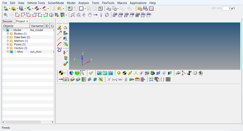
Figure 3. - Click .
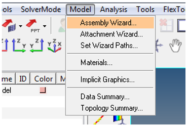
Figure 4.The Car/Small truck - Model Type dialog opens.
- Start MotionView from the installation folder of HyperWorks.
- Building a Full Vehicle Model with Aerodynamic Forces
- The following steps how to make a Full vehicle model with Aerodynamic Forces.
- Select the Full vehicle with driver option from the Model
Type dialog and click Next.
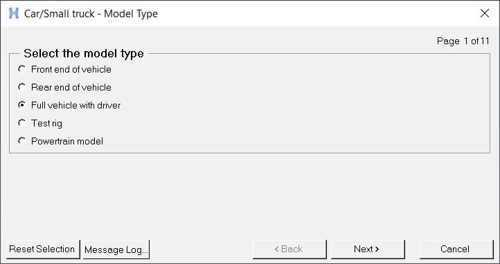
Figure 5. - Select the Aerodynamic Forces on the additional systems
page and complete the model selection.
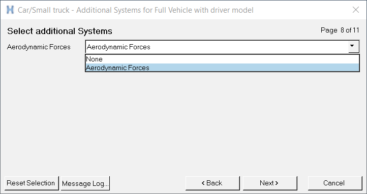
Figure 6.Note: Aerodynamic Forces is now included as a system. - The Full vehicle with driver model including the aerodynamic forces system build
through the Assembly Wizard is displayed in the graphics area.
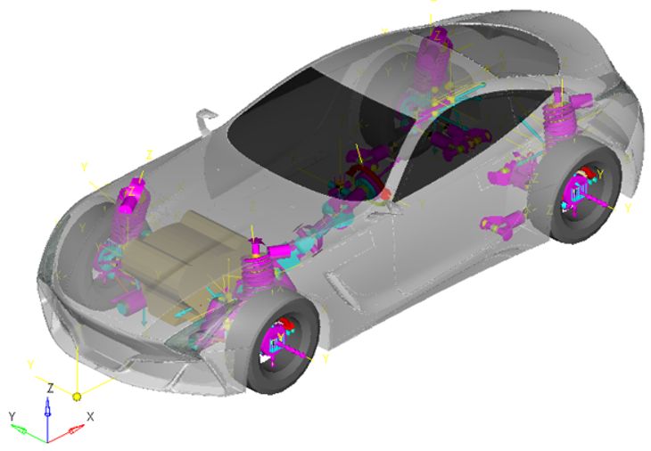
Figure 7. - The subsystems with the Aerodynamic Forces you have selected in the Assembly
Wizard to build the model are displayed in the browser.
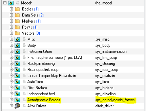
Figure 8.
- Select the Full vehicle with driver option from the Model
Type dialog and click Next.
Aerodynamic Forces Graphical User Interface
- Click on Aerodynamic Forces in the browser to bring up the
Attachments section in the panel area.
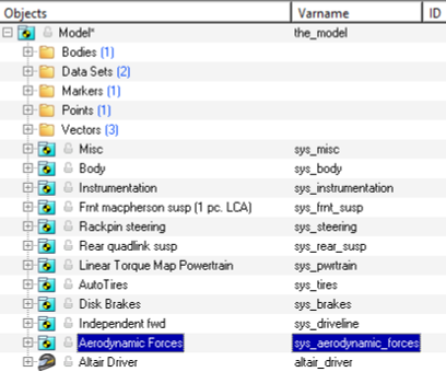
Figure 9.The corresponding panel is displayed.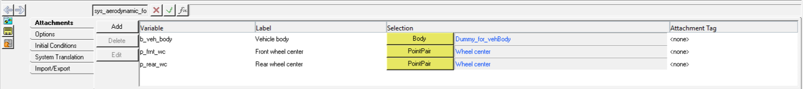
Figure 10.Attachments Description Vehicle Body
*RequiredVehicle body where the action forces of Aerodynamic system is applied. Front wheel center
*RequiredWheel center point pair for front axle. Rear wheel center
*RequiredWheel center point pair for rear axle.
References
- Manfred Mitschke and Henning Wallentowitz, Dynamik der Kraftfahrzeuge, Auflage, Springer, 2004.