Create Panel Structural Elements
The Panel tool recognizes metallic panels or composite panels, which lead to two different configs as the structural property and method available for these configs are different.
-
From the Certification ribbon, click the Panel
tool.

Figure 1. -
When Structural elements are created, a structural property can be selected.
Click
 to define how properties are assigned.
Each structural element can have a structural property assigned to it (optional) in order to run method.
to define how properties are assigned.
Each structural element can have a structural property assigned to it (optional) in order to run method.- Single property
- Assigns the same structuralproperty entity to all designpoints.
- Duplicate and assign property to all
- Creates a new instance of selected structuralproperty and assigns the copy to all designpoints.
- Duplicate and assign property per designpoint
- Creates a new instance of selected structuralproperty per designpoint entity.
-
Set the entity type on the first selector to
Elements.
If only shell elements are selected, panels are recognized as shell elements by face until T-junctions.If the selection includes both shells and bar2/rod elements, panels are recognized as shells surrounded by 1D.
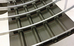
Figure 2. Panel Geometry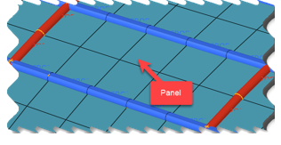
Figure 3. Structural PanelWhile generating stuctural elements of config panel or Generic, you can split them based on the element’s property or the element’s component. On the guide bar, click
to select a Split by
option.The split operation is done after panel detection method from shells and attached 1D.- If split = none, panels are detected based on the description above.
- If split = by property/by component.
The panels are first detected based on T-junctions and further split based on shell property/component.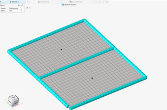
Figure 4. Panel Detection by Topology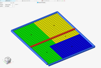
Figure 5. Panel Detection with Post Split by Property -
Specify a structuralproperty entity if the Absorb FE Property checkbox is
unselected.
Otherwise, the tool attempts to absorb a structural property from the element closest to the panel’s center. This structural property is then unique for all elements belonging to the panel.Panel metallic retains thickness and material from the reference element.

Figure 6. Panel MetallicPanel composite creates a copy of the composite property from the reference element.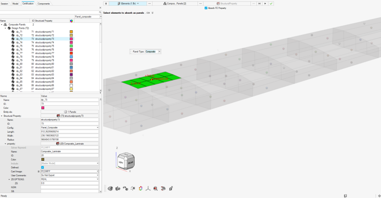
Figure 7. Panel CompositeThe panel width/length and radius of curvature are approximately calculated from the FE model.
-
On the guide bar, click one of the following:
 - Save changes and stay in the tool.
 - Save changes and close the tool.