Create and Assign Structural Properties
Structural properties are meant to be placeholders that hold local information, that can change from one structural element to another, useful for method evaluation. They usually contain extra information not directly available from FE entities or results.
- Generic
- Beam
- Rivet
- Spring
- Panel Composite
- Panel Metallic
Structural elements can have a structural property of the same configuration assigned to them. Each configuration comes with a different set of available data names that are usually required in typical methods.
Structural properties, unlike materials or properties, can be dynamically extended with user-defined attributes in the Entity Editor (see Add Data Names).
-
From the Certification ribbon, Property tool group, click the
Create tool.

Figure 1. -
Assign a configuration and define any parameters in the dialog and then click
Close.
Configuration Description Beam Beam structural properties refer to a Material entity and a Beamsection entity. They also have a Length data name which represents the physical length of the Member (column) that needs to be considered in methods (that length is multiplied by the constraint factor in buckling length calculation). When a structural property is created from Beam structural element detection, the length defaults to the total length of the beam elements absorbed.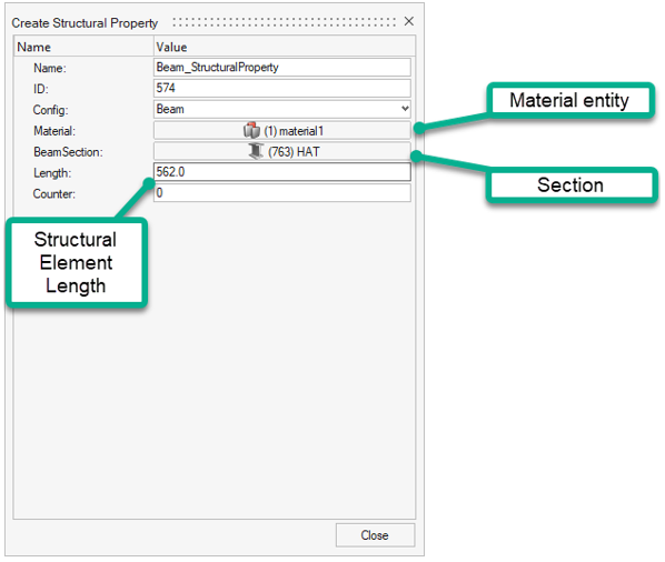
Figure 2.Rivet Rivet structural properties contain, by default, the Rivet diameter. This diameter is considered in the size of the extraction area where far field fluxes are extracted.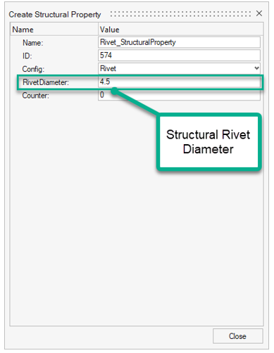
Figure 3.Panel Metallic Panel metallic structural properties contain reference to:- Panel thickness (constant for the whole panel)
- Metallic material
- Panel dimensions (width/length/radius of curvature)

Figure 4.Panel Composite Panel composite structural properties contain reference to:- Panel dimensions (width/length/Radius of curvature)
- Composite property
For OptiStruct/Nastran solver profiles, the property used is of type PCOMP/PCOMPG. The sequence information (ply thicknesses, orientations, and materials) are extracted from this property.
A structural property assigned without reference to a property runs using a direct elemental property instead of a “panel-level” property.
Figure 5.Spring Spring structural properties contain reference to:- Bush property
For OptiStruct/Nastran solver profiles, the property used is of type PBUSH.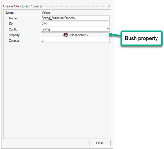
Figure 6.Generic Generic structural properties have no default.
-
From the Property tool group, click the Assign
tool.

Figure 7. -
On the guide bar, click
 and select an option for how structural properties are assigned to design
points.
and select an option for how structural properties are assigned to design
points.
- Assign selected property
- Assigns the same structuralproperty entity to all designpoints.
- Duplicate and assign property to all
- Creates a new instance of selected structuralproperty and assigns the copy to all designpoints.
- Duplicate and assign property per designpoint
- Creates a new instance of selected structuralproperty per designpoint entity.
-
On the guide bar, click one of the following:
 - Save changes and stay in the tool.
 - Save changes and close the tool.
- Click the satellite icon
 that appears when you hover over the Property
tool to filter a list of structural properties.
that appears when you hover over the Property
tool to filter a list of structural properties. - As an entity referenced by a designpoint, the Structural Property can also be assigned from the Certification Browser.
Add Data Names
-
Use the new dialog to fulfill the details of data names to be added.
The following are descriptions of the attribute columns and behaviors in the table editor. (see Figure 8):
- Dataname
- The actual internal name of the added data name saved in the binary file.
- Display Name
- The label displayed in the Entity Editor.
- Basic Type
- Defines the type of the data name.
- Default Value
- Defines the default value displayed in the user interface.
- Allowables
- Provides a list of allowable entries.
- Differentiator
- Defines a special rendering of the data name in the user interface. It defaults to Unspecified. Other options are:
- Editable
- Controls whether you can change value in the user interface.
- Visible
- Controls whether the data names is shown in the user interface.
- Parent Dataname
- If a previously defined data name is set (by its Dataname field) in this cell, the currently defined data name becomes a child of the above-mentioned Parent Dataname. Parent data names are rendered as a group that can be expanded/collapsed.
- Expand Children
- Controls the way children data names are expanded. Valid values are: Expanded:
- Tooltip
- Shows the tooltip when the mouse hovers over the display name.
The other column headers available in the table editor are reserved for future use.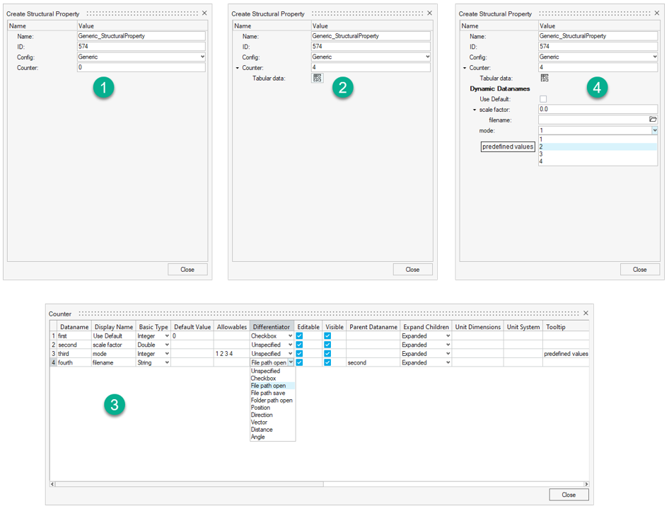
Figure 8.