Edit
Displays the data contained in the selected TableView cell.
 Figure 1. Edit icon
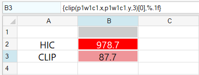
Figure 2. Cell B3 selected, cell highlighted and content displayed in Edit bar
The Edit tool supports multiple lines of data. Press Alt + Enter to add a line break to a single cell.
Evaluate Mode
Change cell data to evaluated or unevaluated mode using the View toolbar Evaluate
icon, ![]() . Templex expressions are
visible in the cell when you click the Evaluate icon.
. Templex expressions are
visible in the cell when you click the Evaluate icon.

Figure 3. View toolbar, Evaluate icon selected