Optimization of Composite Structures
A comprehensive optimization solution aimed at guiding and simplifying the design of laminate composite structures.
- Phase I - Concept. Free-sizing optimization is used to generate design concepts, while considering global responses and optional manufacturing constraints.
- Phase II - System. Sizing optimization, with ply-based modeling, is performed to control the thickness of each ply bundle, while considering all design responses and optional manufacturing constraints.
- Phase III - Detail. Ply-stacking optimization is applied to determine the detailed stacking sequence, again while considering all behavioral responses, manufacturing constraints and various ply book rules.
While these techniques can be applied independently, it is recommended to use them together as a three-phase integrated process guiding the design from concept to completion. This is particularly important when manufacturing constraints are involved. In order to satisfy such constraints at the finishing stage, they should be incorporated at the beginning so that the design concept can be carried forward. Automated tools are provided to facilitate the transition between the design optimization phases.
Free-sizing Optimization
Create design concepts that utilize all the potential of a composite structure where both structure and material can be designed simultaneously.
By varying the thickness of each ply with a particular fiber orientation for every element, the total laminate thickness can change 'continuously' throughout the structure, and at the same time, the optimal composition of the composite laminate at every point (element) is achieved simultaneously. At this stage, a super-ply concept should be adopted, in which each available fiber orientation is assigned a super-ply whose thickness is free-sized. In other words, a super-ply is the total designable thickness of a particular fiber orientation. In addition, in order to neutralize the effect of ply stacking sequence, the SMEAR option is usually a good choice for this design phase unless it is intended to follow through with the stacking preference of the super-ply laminate model.
- Lower and upper bounds on the total thickness of the laminate
- Lower and upper bounds on the thickness of individual orientations
- Lower and upper bounds on the thickness percentage of individual orientations
- Constant thickness of individual orientations
- Thickness balancing between two given orientations
As for the constraints on laminate thickness, ply thickness and thickness percentage, these can be applied locally through the definition of element sets. Therefore, multiple instances of these constraints are supported. Advantages include being able to allow different constraints in different regions while preserving the continuity of plies. For example, different thickness requirements in critical regions, such as bolted areas, can be factored into the design process. Additionally, zone based free-sizing (parameter) optimization can be performed. Zones are defined through groups of elements and there can be elements that do not belong to any zone. Zones are typically defined to simplify the design interpretation process and improve manufacturability. Instead of having to interpret manufacturable zones from the solution of a free-sizing (parameter) optimization, the optimization is run based on pre-defined zones. While the interpretation process is simplified, there is a loss in design freedom as now the optimization is restricted to some extent due to the defined zones.
The standard result from a free-sizing optimization is the thickness contribution of each orientation defined on the PCOMP(G) or STACK card referenced by the DSIZE card in the optimal laminate design. But, using free-sizing as part of the three-phase composite design and optimization process, and the mechanism to automatically generate an input file for phase two of this process, an additional level of detail/results can be drilled down to in terms of the thickness contributions per orientation. The automatically generated input file for phase two contains ply bundle data that can be reviewed in HyperMesh.
A ply bundle is a continuous stack of plies of the same shape (or coverage area). Each super-ply results in the formation of 4 ply bundles. This is the default behavior and can be changed, that is a different number of ply bundles can be requested from the super-plies. However, in most cases, it is recommended to use the default approach.
Ply-based Sizing (Parameter) Optimization
Ply-based Laminate Modeling
Complimentary to the conventional property-based composite definition, a new ply-based modeling technique was introduced in OptiStruct 9.0. In this format, laminates are defined in terms of ply entities and stacking sequences, which reflect the native language of ‘ply-book’ standards to composite laminate modeling and manufacturing. This is also analogous with how a laminate composite is manufactured. The PLY card specifies the thickness, orientation and material data for each ply, as well as its layout in the structure. The STACK card ‘glues’ the PLYs together to produce the laminate structure. Properties of every zone of unique laminate lay-ups are uniquely, albeit implicitly, defined. This allows you to simply focus on the physical buildup of the composite structure and eliminates the burden associated with identifying patches (PCOMPs) of unique lay-ups, which can be especially complicated for a free-sizing generated design.
Ply-based Optimization
In property-based sizing (parameter) optimization, the designable entities are the ply thicknesses associated with the PCOMP(G) properties. In ply-based sizing (parameter) optimization, the PLY thicknesses are directly selected as designable entities. This approach greatly simplifies the design variables definition, since ply continuity across patches is automatically taken into account.
As with free-sizing optimization, several composite manufacturing constraints are available to control the thickness of the laminate or the thicknesses of specific orientations. These constraints are defined on the DCOMP card and should generally be inherited from the concept phase. A mechanism exists whereby the composite manufacturing constraints defined in the free-sizing phase are automatically carried over into the ply sizing (parameter) optimization phase. This is part of the same mechanism that also generates the input file for the ply based sizing (parameter) optimization (phase 2), containing ply bundles as explained in the section on Free-sizing Optimization. Through this, the ply bundles are automatically set up for optimization with the necessary DESVAR and DVPREL cards defined. The ply bundles are now ready to be sized to determine the optimum thickness per bundle per fiber orientation.
In addition, discrete optimization is automatically activated when TMANUF, the thickness of the basic manufacturable ply, is specified for the PLY associated with a given design variable. This feature forces ply bundles to reach thicknesses reflecting a discrete number of physical plies.
Therefore, from a ply bundle sizing (parameter) optimization, the number of plies required per orientation can be established.
Typically, additional behavioral constraints such as failure, strain, etc. are added to the problem formulation at this stage.
Stacking Sequence Optimization
Composite plies are shuffled to determine the optimal stacking sequence for the given design optimization problem while also satisfying additional manufacturing constraints.
- The stacking sequence should not contain any section with more than a given number of successive plies of same orientation.
- The 45° and -45° orientations should be paired together.
- The cover and/or core sections should follow a predefined stacking sequence.
Using the three-phase process, composite plies are generated from running a discrete ply bundle sizing optimization (through TMANUF) in phase 2. Additionally, an input file for phase 3, i.e. stacking sequence optimization, is automatically generated from phase 2.
An efficient proprietary technique is developed to allow the process to evaluate a huge number of stacking combinations from both performance and manufacturability perspectives.
Phase Transitions in the Optimization of Composite Structures
In order to simplify the transition between the three design phases, OptiStruct automatically generates input decks after the free-sizing optimization or the sizing (parameter) optimization stages have converged.
OUTPUT,FSTOSZ (free-sizing to sizing) is an output request that can be used during the free-sizing (parameter) optimization phase to write a ply-based sizing optimization input deck. For each orientation, the composite interpreter identifies regions of similar thickness and creates PLYs for these regions. The resulting deck contains PCOMPP, STACK, PLY, and SET cards describing the ply-based composite model, as well as DCOMP, DESVAR, and DVPREL cards defining the optimization data. Manufacturing constraints are transferred from the DSIZE card to the DCOMP card. Typically, additional design responses such as stress/failure constraints would be introduced at this optimization stage.
OUTPUT,SZTOSH (sizing to shuffling) is an output request that can be used during the ply-based sizing optimization stage to write a ply stacking optimization input deck. Each PLY bundle is divided into multiple PLYs whose thickness is equal to the manufacturable thickness TMANUF, and the STACK card is updated accordingly. The DESVAR and DVPREL cards from the previous stage are removed, and a bare DSHUFFLE card is introduced. As required by the design, additional ply-book rules or manufacturing constraints can be defined on the DSHUFFLE card.
Rectangular Composite Panel Example
A rectangular composite panel is clamped on one side and subjected to a tip load on the other side.
This simple model can be used to demonstrate how the three phases of the composite optimization package interact with each other to ultimately generate a manufacturable design.
Free-sizing (Parameter) Optimization
DSIZE 1 PCOMP 1
+ COMP LAMTHK 3.2
+ COMP PLYPCT ALL 0.10
+ COMP BALANCE 45.0 -45.0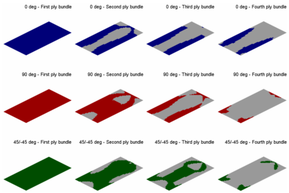
Figure 1. Ply Bundles After Ply-based Interpretation
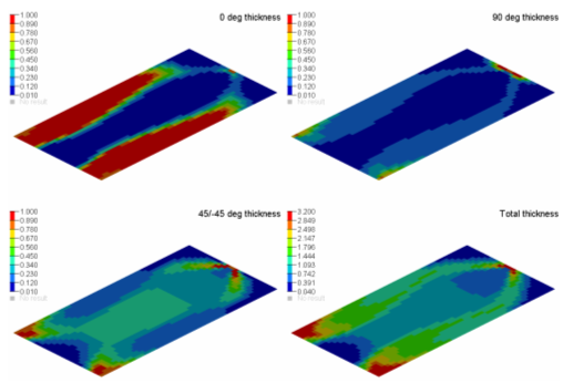
Figure 2. Thicknesses After Free-sizing Optimization
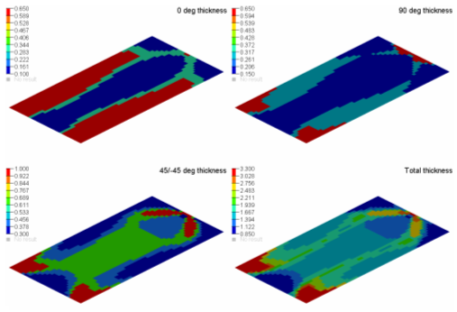
Figure 3. Thicknesses After Ply-based Interpretation
Ply-based Sizing (Parameter) Optimization
Once a concept design has been established, additional performance measures should be introduced. In this example, you are changing the formulation to minimize the volume while constraining the maximum principal stress in every ply. Also, the composite manufacturing constraints from the previous stage are preserved and transferred to the DCOMP card.
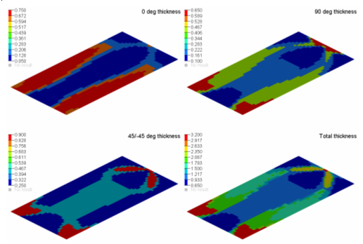
Figure 4. Thicknesses After Ply-based Sizing Optimization
Ply Stacking Optimization
DSHUFFLE 1 STACK 1
+ MAXSUCC ALL 4
+ PAIR 45.0 -45.0 REVERSE
The optimization converges in seven iterations, and the resulting stacking sequence strictly satisfies all constraints.
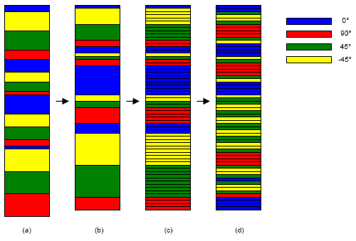
Figure 5. Stacking Sequences During Sizing and Shuffling Optimization
Since most plies only cover part of the laminate structure, the stacking sequence for each zone of unique lay-ups is different from the one illustrated above. However, the manufacturing feasibility is evaluated for every individual zone.