_nl.out file
An ASCII format results file which can be used for monitoring and debugging of nonlinear analysis.
File Creation
This file is always created for any nonlinear static or nonlinear transient run.
File Contents
This file provides detailed information regarding the nonlinear solution progress, and can be used to monitor nonlinear runs and if required, investigate and debug any non-convergent nonlinear runs, including in conjunction with the _nl.h3d file (refer to Runtime Monitoring for more information).
File Format
The file contains nonlinear solution parameters and solution progress information for each subcase within the model. The format for each such subcase is the same, and for each subcase, it can be considered as consisting of two sections, the header section and the main section. The header section, outlines the nonlinear control parameters and the subsequent main section consists of the nonlinear solution progress summary for the particular subcase of interest.
- Header section (Nonlinear Control Parameters)
- Main section (Nonlinear Iteration Summary)
The following sections illustrate examples of both the header and main sections, along with an explanation of each item within the sections.
Header Section (Nonlinear Control Parameters)

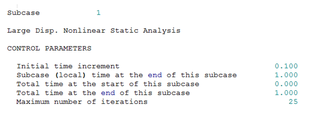
Figure 1.
- Initial time increment
Depending on the type of analysis, this is calculated based on corresponding fields on NLPARM, TSTEP, or TSTEPNL (for instance, DT on NLPARM can define the Initial time increment).
- Subcase (local) time at the end of this subcase
Depending on the type of analysis, this is calculated based on corresponding fields on NLPARM, TSTEP, or TSTEPNL (for instance, TTERM on NLPARM can define the subcase (local) termination time).
- Total time at the start of this subcase and Total time at the end of this
subcase
Depends on model setup. For continued subcases, the total time adds up for subsequent subcases.
- Maximum number of iterations
MAXITER field on NLPARM

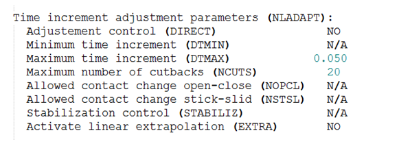
Figure 2.
- Tolerance Disp. (EPSU): EPSU field on NLPARM
- Tolerance Force (EPSP): EPSP field on NLPARM
- Tolerance Work (EPSW): EPSW field on NLPARM

Figure 3.
The Time increment adjustment factors are used in adaptive time-stepping. The labels below say “default for SMDISP” or “default for LGDISP” in this example. However, this label can change based on the time increment adjustment system for a particular model (for instance, if the Expert system is turned on).

Figure 4.

Figure 5.
Main Section (Nonlinear Iteration Summary)
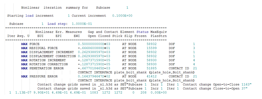
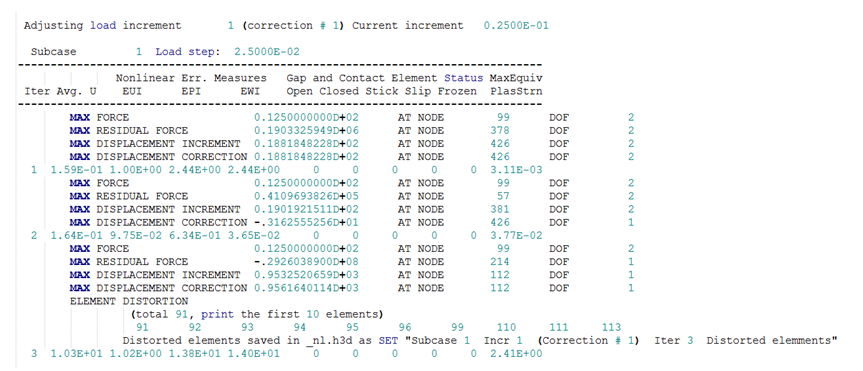
Nonlinear Iteration Summary table for Nonlinear Analysis.

Figure 6. Model with Contacts

Figure 7. Model with Element Distortion
- Avg. U
- Represents the average displacement of all grids for a particular iteration for a subcase
- EUI
- Represents the relative error in displacements
- EPI
- Represents the relative error in terms of load
- EWI
- Represents the relative error in terms of work
- MaxEquiv Plststrn
- Represents the maximum equivalent plastic strain
- Gap and Contact Element Status
- The columns are self-explanatory.
- Table Row Items within each increment
- MAX FORCE
- Maximum external force of all degrees of freedom.
- MAX RESIDUAL FORCE
- Maximum difference between the internal force and external force of all degrees of freedom. This is the unbalanced load at this iteration.
- MAX DISPLACEMENT INCREMENT
- Maximum incremental translational displacement of all degrees of freedom. It includes the current and all previous displacement corrections for this particular increment. Its printed value is reset at the end of each increment.
- MAX DISPLACEMENT CORRECTION
- Maximum translational displacement correction per iteration of all degrees of freedom. It is the correction applied to the displacement for each particular iteration. Its value varies from iteration to iteration, depending on the amount of displacement correction to be applied.
- MAX ROTATION INCREMENT
- Maximum incremental rotation of all degrees of freedom. It includes the current and all previous rotation corrections for this particular increment. Its printed value is reset at the end of each increment.
- MAX ROTATION CORRECTION
- Maximum rotation correction per iteration of all degrees of freedom. It is the correction applied to the rotation for each particular iteration. Its value varies from iteration to iteration, depending on the amount of rotation correction to be applied.
- MAX PENETRATION ERROR
- This is only applicable to models which contain Contact. It is the maximum penetration error among all contact interfaces in the model. The name, ID, and associated node ID of the CONTACT INTERFACE of interest is also printed.
- MAX PRESSURE ERROR
- This is only applicable to models which contain Contact. It is the maximum pressure error among all contact interfaces in the model. The name, ID, and associated node ID of the CONTACT INTERFACE of interest is also printed.
- Grids associated with Contact Change
The total number grids associated with a changed contact status for this iteration is turned OFF by default. Its printing can be controlled via the CONTCHG field of the NLPRINT Bulk Data Entry.
Grid sets of each of the below associated contact changes are also printed to the corresponding _nl.h3d file, if NLMON,DISP,ITER/INC Bulk/Subcase pair exists.- CONTACT CHANGE OPEN-TO-CLOSE
- The number of grids associated with a changed contact status for this iteration from Open to Close are printed.
- CONTACT CHANGE CLOSE-TO-OPEN
- The number of grids associated with a changed contact status for this iteration from Close to Open are printed.
- CONTACT CHANGE STICK-TO-SLIP
- The number of grids associated with a changed contact status for this iteration from Stick to Slip are printed.
- CONTACT CHANGE SLIP-TO-STICK
- The number of grids associated with a changed contact status for this iteration from Slip to Stick are printed.
- ELEMENT DISTORTION (total #, print # elements)
- The total number of elements which are distorted at a particular iteration. The default number of elements printed is 10, and this can be controlled using the ELEMDIST field of the NLPRINT Bulk Data Entry.
Grid sets of each of the above distorted elements are printed to the corresponding _nl.h3d file, if NLMON,DISP,ITER/INC Bulk/Subcase pair exists.