Feko is a comprehensive electromagnetic solver with multiple solution methods that is used for electromagnetic field analyses
involving 3D objects of arbitrary shapes.
EDITFEKO is used to construct advanced models (both the geometry and solution requirements) using a high-level scripting language
which includes loops and conditional statements.
One of the key features in Feko is that it includes a broad set of unique and hybridised solution methods. Effective use of Feko features requires an understanding of the available methods.
Feko offers state-of-the-art optimisation engines based on generic algorithm (GA) and other methods, which can be used
to automatically optimise the design and determine the optimum solution.
Feko writes all the results to an ASCII output file .out as well as a binary output file .bof for usage by POSTFEKO. Use the .out file to obtain additional information about the solution.
CADFEKO and POSTFEKO have a powerful, fast, lightweight scripting language integrated into the application allowing you to create
models, get hold of simulation results and model configuration information as well as manipulation of data and automate
repetitive tasks.
CADFEKO and POSTFEKO have a powerful, fast, lightweight scripting language integrated into the application that allows you to create models,
get hold of simulation results and model configuration information and much more.
A mesh of surface triangles in the shape of a flat parallelogram can be created with this card. In general, this card
is replaced by the PM card. This card should only be used when the user wants to force the very regular meshing that
this card produces.
The CB card can be used to change geometry element labels that have been previously defined. Labels that are associated
with points, segments, triangles, cuboids, polygonal plates and tetrahedral elements can be updated.
Domain decomposition can be used to store parts of a method of moments solution in a file to be reused in future simulations. The stored part must remain static but the rest of the model
can change.
The DP card is used to define points in space. These points are used to define the extent and orientation of other geometric
entities and to locate excitations.
The DZ card is used to create a cylindrical shell, meshed into cuboidal elements for using the volume equivalence principle
in the method of moments. The meshing parameters as set at the IP card are used, and the medium as set at the ME card
is assigned to all created cuboidal elements.
The FM card is used to instruct the Feko solver to calculate the solution using accelerated methods, for example, using the multilevel fast multipole method (MLFMM) or adaptive cross-approximation (ACA). An option is available to apply compression to looped plane wave sources.
Options related to the Feko solution parameters is set using the FP card. The basis functions used when using FEM or MoM is set globally or on specific labels.
The IN card is used to include external files. These files may be other .pre files (which are included as if they were part of the master file) or mesh data files containing wire segments, triangles,
quadrangles, tetrahedral volume elements and/or polygonal plates (in FEMAP neutral, ASCII format, NASTRAN, AutoCAD DXF,
NEC model, CONCEPT geometry, STL, PATRAN neutral, ANSYS CDB, ABAQUS, GiD or I-DEAS UNV mesh files).
This card creates a mesh of surface triangles in the shape of circular region with or without a hole. It is also possible
to create an elliptical region.
With this card, a modal port boundary condition may be applied on the boundary of a finite element method (FEM) region. A modal port essentially represents an infinitely long guided wave structure (transmission line) connected to
a dielectric volume modelled with FEM.
This card must be used to distinguish the different media and to create segments and triangles (metallic or dielectric)
within or on the surface of dielectrics solved with FEM or VEP as well as MoM/MLFMM.
The PH card creates a triangular or quadrangular plate with a circular or elliptical hole as shown in the card. The hole
can be used, for example, to attach a cylinder (ZY card) to the plate and it can be filled with the KR card.
A surface mesh of triangles in the shape of a polygon is created by using the PM card. The PM card also allows the specification
of interior mesh points. The PM card should generally be used in favour of other cards that create flat surface meshes
with straight edges.
This card creates a dielectric or magnetic cuboid, meshed into smaller cuboidal volume elements, for solving with the
volume equivalence principle in the MoM.
The RM card provides a sophisticated remeshing and adaptive mesh refinement facility. Most types of meshes (surface mesh
with triangular patches, wire segment mesh, cuboidal volume elements) created by any option supported in Feko (for example, direct creation in PREFEKO with cards, but also import from NASTRAN, FEMAP, PATRAN and the rest) can be used as a basis, and one can then apply
either a local or a global mesh refinement. Unfortunately in Feko Suite 5.4 there is still a restriction that tetrahedral volume elements as used for the FEM cannot be refined with the RM card.
With the TG card, the already entered geometric elements (triangles, segments and the rest) can be translated, rotated,
mirrored and/or scaled. It is also possible to duplicate structures.
This card defines the parameters for the uniform theory of diffraction (UTD) for polygonal plates and cylinders, faceted UTD for curved surfaces and ray launching geometrical optics (RL-GO).
The WA card is used to define all windscreen antenna solution elements. This would include all elements in close proximity
to the finite glass structure and can consist of either segments or triangles (all defined by labels).
The WR card is used to define a dielectric windscreen reference plane. Geometrically this surface is not part of the electromagnetic
model and is used simply to determine the curvature factor between the two elements on the windscreen.
When meshing a model, you can either use the automatic meshing algorithm to calculate the appropriate mesh settings
or you can specify the mesh sizes. When you specify the mesh sizes, the mesh sizes should adhere to certain guidelines.
Feko integrates with various products within Altair Simulation Products such as HyperStudy. Integration with third-party products is also supported through the powerful scripting and plug-in infrastructure.
Feko creates and uses many different file types. It is useful to know what is stored in the various files and weather they were
created by Feko and if it is safe to delete them. The files are grouped as either native files that have been created by Feko or non-native files that are supported by Feko. Non-native files are often exported by Feko even if the formats are not under the control of the Feko development team.
This card defines the parameters for the uniform theory of diffraction (UTD) for polygonal plates and cylinders, faceted UTD for curved surfaces and ray launching geometrical optics (RL-GO).
With this option the UTD parameters for faceted
UTD for planar and curved faces are specified.
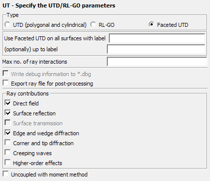
Parameters:
Use faceted UTD on all surfaces with label
The label to which the faceted UTD should be
applied
(optionally) up to label
The label up to which the faceted UTD should be
applied. Faceted UTD will not be applied to labels
outside of the range between this field and the label in the previous field.
Max no. of ray interactions
This parameter gives the maximal number of ray-interactions. If for example, the
parameter is set to 3, a ray can have 3 reflections. If set to 0, only direct rays are
taken into account.
Export ray file for post-processing
When this item is checked the ray information is exported to the
.bof and .ray files. Activate this option if
ray paths are to be displayed in POSTFEKO where the ray
information is read from the .bof file. The exported ray
information may result in a large .ray file and a dramatic
increase in the .bof file size. For parallel runs the
run-time can also increase significantly when exporting ray data.
The following abbreviations are used in the .ray file and POSTFEKO:
·: Creeping wave intermediate point on geometry
surface
B: Diffraction at an edge
D: Diffraction at a corner or a tip
K: Diffraction at a wedge
Q: Source point
R: Reflection
S: Observation point
C: Creeping wave attaching and shedding point on
geometry surface
V: Reflection at the shadow boundary of a creeping
wave
Ray contributions
Determines which ray contributions to take into account.
Direct field
Direct rays are taken into account.
Surface reflection
Rays reflected from planar and curved surfaces are taken into account.
Surface transmission
Rays transmitted (refracted) from non-metallic planar and curved surfaces are
taken into account.
Edge and wedge diffraction
Diffraction on edges and wedges are taken into account.
Corner and tip diffraction
Diffraction at corners and tips are taken into account.
Creeping waves
Creeping waves on curved surfaces.
Higher-order effects
Only multiple reflections plus one edge/wedge diffraction at any position along
the ray path can be computed. This option is only active if Surface
reflection and Edge and Wedge diffraction
check boxes are selected and the Max. no. of ray
interactions is larger than 1.
Increasing the type and number of ray interactions increases
accuracy and the computation time. The user should therefore make a compromise between the
number of ray interactions and the ray contributions. Choices made in this card should be made
on physical considerations to get optimal use from the UTD
formulation.
The following restrictions apply for the faceted UTD:
Only PEC structures are allowed (no dielectric bodies, thin dielectric sheets or
coatings are allowed).