Create Voxel Meshes
Use the Voxel: Create tool to create voxel meshes.
-
From the Define group, select .

Figure 1.A guide bar will appear.
Figure 2. -
Define voxel options.
-
On the guide bar, click
 .
The Options dialog opens.
.
The Options dialog opens.
- Intersections and Voids (default)
- Voids only
- Intersections only
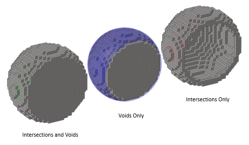
Figure 3.
-
On the guide bar, click
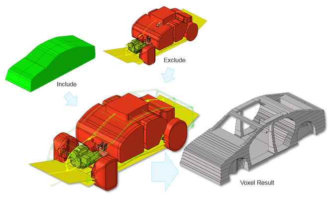
Figure 4.
When the voxels are generated two new entities are created and append to the Model Browser, Design Spaces and Symmetry Planes. Symmetry Planes will only appear if the Symmetry option is used during voxel generation. Both of these entities store and persist the necessary information for further downstream use, and are saved in the.hm binary file. For example; if the non-design package space changes, you can simply select and update the exclude entities and re-generate the voxels.
Modify the Design Space entity by selecting it in the browser and then invoking the Voxel: Create tool. Changing the voxel size, the include/exclude content, and symmetry usage is all possible. The Output Components can only be modified in the in the Model Browser, Entity Editor. Voxels can be organized into one or many components to group the regions into representative manufacturable parts, such as castings or machined parts for example. Typically, these sort of design variables (or regions) have specific topology optimization options applied such as draw direction for improved manufacturability.
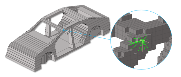
Figure 5.
Figure 6.