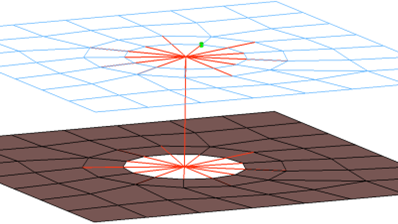
Creates CERIG element for the head and LINK10 element for body. The head elements project
and connect to the nodes of the adjoining shell elements which form the hole and also
the second row of nodes which form the washer layer. The head only connects to every
other node on the washer layer. The connector location can either be on the edge of the
hole, center of the hole, midpoint in between the two holes or on the second row of
nodes which form the washer layer. Properties and materials are also created for the
LINK10 element. Figure 1.