Creates CERIG elements for the head and the LINK10 element for body. There are two
individual CERIG elements at the head of the connection, one to connect to the inner row
of nodes, the other to connect to the washer layer nodes. The connector location can
either be on the edge of the hole, center of the hole, midpoint in between the two holes
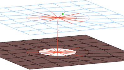
or on the second row of nodes which form the washer layer. Property and material cards
are created for the LINK10 element. Figure 1.