OS-T: 1395 Acoustic Analysis of Speaker Using RADSND
This tutorial demonstrates how to perform acoustic analysis of 2.1 speakers using the RADSND Method.
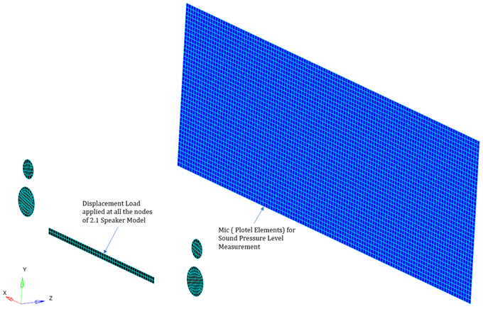
Figure 1. FE Model
For this model, a frequency response analysis is performed to measure the sound pressure level at the mic points. In Figure 1, the 2.1 speaker is illustrated by the shell elements on which harmonic displacement is applied at each node to make them vibrate. The vibration of the speakers produces sound waves that are measured at the mic points. The results, displacements and sound pressure levels, will be reviewed in HyperView.
Launch HyperMesh and Set the OptiStruct User Profile
Open the Model
Set Up the Model
In this step you will create the material and property, and assign the property.
Create the Material
- In the Model Browser, right-click and select from the context menu.
- For Name, enter Aluminum.
- Click Color and select a color from the color palette.
- For Card Image, select MAT1 from the drop-down menu.
- For E, enter 70E9.
- For NU, enter 0.3.
Create the Property
- In the Model Browser, right-click and select from the context menu.
- For Name, enter Shell.
- Click Color and select a color from the color palette.
- For Card Image, select PSHELL from the drop-down menu and click Yes to confirm.
- For Material, select .
- In the Select Material dialog, select Aluminum from the list of materials and click OK.
- For Thickness, enter 0.01.
Assign the Property
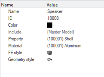
Figure 2.
Apply Loads and Boundary Conditions
In this step you will create load collectors and set boundary conditions.
Create SPC Load Collector
- In the Model Browser, right-click and select from the context menu.
- For Name, enter SPC.
- Click Color and select a color from the color palette.
- Toggle Analysis panel and select the constraints option.
- Select all nodes of the speaker and activate all DOF and enter 0 for each.
- For Load Type, select SPC and click return.
Create SPCD Load Collector
- In the Model Browser, right-click and select from the context menu.
- For Name, enter SPCD.
- Click Color and select a color from the color palette.
- Toggle Analysis panel and select the constraints option.
- Select all nodes of the speaker and activate DOF 3 and enter 1E-5.
- For Load Type, select SPCD and click return.
Create a Set of Frequencies
Create a Frequency Range Table
-
Click the Table icon
 below TABLED1_NUM and enter:
- For x(1) = 0.0.
- For y(1) = 1.0.
- Fo x(2) = 100.0.
- For y(2) = 1.0.
Create a Frequency Dependent Load
Create a Dynamic Load
- In the Model Browser, right-click and select from the context menu.
- For Name, enter Dload.
- Click Color and select a color from the color palette.
- For Card Image, select DLOAD from the drop-down menu.
- For S, enter 1.
- For DLOAD_NUM=, enter 1.
- For S, enter 1.
- For L, select RLOAD.
Create LOADSTEP
Set Up a RADSND Panel
In this step you will create and set up a RADSND panel.
Create a Surface Nodes Set
- In the Model Browser, right-click and select from the context menu.
- For Name, enter Surface_Nodes.
- For Card Image, select SET_GRID from the drop-down menu.
- For Entity IDs, select Nodes, then select all nodes of the speaker component, and click proceed.
Create a Mic Nodes Set
- In the Model Browser, right-click and select from the context menu.
- For Name, enter Mic.
- For Card Image, select SET_GRID from the drop-down menu.
- For Entity IDs, select Nodes, then select all nodes of the receiver component, and click proceed.
Create PANELG
- In the Model Browser, right-click and select from the context menu.
- For Name, enter PANEL.
- For Card Image, select PANELG from the drop-down menu.
- For Type, select SOUND.
- For GSID, select Surface_Nodes from the list of sets.
Create RADSND
- In the Model Browser, right-click and select from the context menu.
- For Name, enter RADSND.
- For Card Image, select RADSND from the drop-down menu.
- For Entity IDs, select Mic from the list of sets.
- For RADSND_NUM_PANEL, enter 1.
- For PID, select PANEL from the list of sets.
Define Output Control Parameters
-
In the control cards page PARAM, under PARAM, select
SPLC, SPLREFDB and
SPLRHO and enter the values, as shown below:
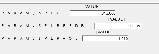
Figure 3.
Submit the Job
-
From the Analysis page, click the OptiStruct
panel.
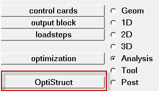
Figure 4.
View the Results
-
On the toolbar, click
 (Contour).
-
Under Result type, from the second drop-down menu, select Sound
Pressure Level and select receiver for
components.
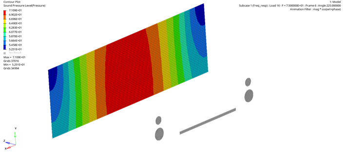
Figure 5.