Internal Superelements
Superelement or DMIG (Direct Matrix Input) approach is a known industry standard to efficiently reduce out the user-defined components to the specified interface grids and this method helps improve the performance of finite element analysis when used properly.
Factorization of assembled matrices is computationally expensive for Implicit Finite Element analysis. The cost is even higher if the factorization has to be repeated multiple times such as for time domain or frequency domain dynamic analysis.
For more information about superelements, refer to Direct Matrix Input (Superelements) in the User Guide.
Standard Superelement versus Internal Superelement
- DMIG generation run: the matrix reduction of components
- Residual run: the final assembly run which uses DMIG
With the Internal superelement process, both DMIG generation run and residual run are performed at the same time.
The main benefit of the Internal superelement process is to be able to retain the model hierarchy, similar to the full model analysis (which does not use any DMIG) and it is very easy to switch from the internal superelement process to full model analysis.
Input Data
- SUPER: Assigns a subcase(s) to a superelement or set of superelements
- SESET: Defines interior grids.
- SEQSET: Assigning modal coordinate
- SECSET: Defines the boundary degrees-of-freedom to be free (c-set) during the calculations for the component mode synthesis
- SETREE: Specifies the superelement reduction order
- CSUPEXT: Assigns the exterior points to a superelement
Define Superelements in OptiStruct
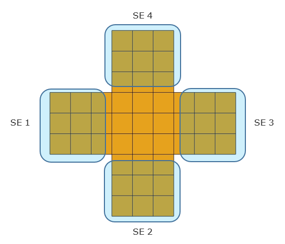
Figure 1. Superelement Definition
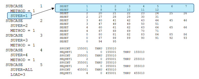
Figure 2. Subcase Definition of Superelements
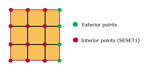
Figure 3. Exterior and Interior Points Defined by CSUPEXT
Alternatively, you can explicitly pick certain grids as exterior points using CSUPEXT. This can be used to ensure that the chosen grids remain as the exterior points.
Review Superelements
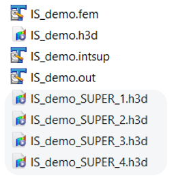
Figure 4. Superelement Matrices Stored in the h3d Files
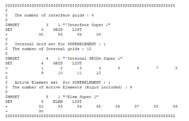
Figure 5. Interior and Exterior Points for each Superelement. from the .intsup file
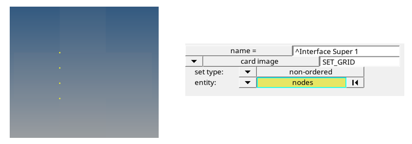
Figure 6. Exterior Points Defined by OptiStruct and the Corresponding Set
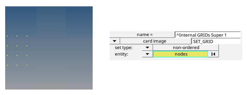
Figure 7. Interior Points User-Defined and the Corresponding Set
Recovery of Results
Figure 8.
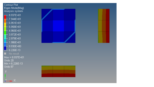
Figure 9.
Multi-level Superelement Tree
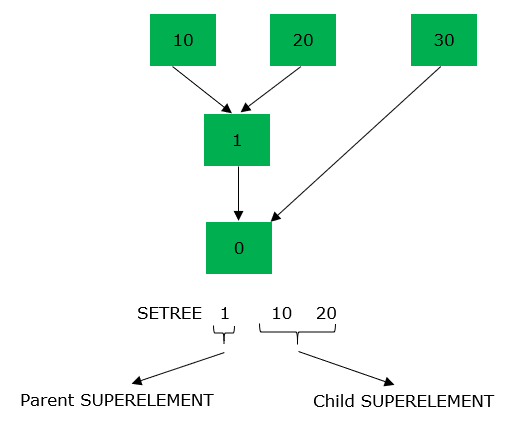
Figure 10. Multi-level Superelement Tree
Comments
- A job involving superelements will be skipped if the corresponding
.h3d files are already present in the working
directory. In such cases:
- The .h3d files for specific superelements can be deleted and the corresponding new superelements would be re-generated by the job
- PARAM,ISGENH3D,YES will initialize the generation, even if the previously generated .h3d files are present in the directory
- When the same Grid point is defined in SESET, as well as in CSUPEXT, the Grid point in CSUPEXT is considered.
- Currently, optimization is not supported with internal superelements.