Global-Local Analysis (Submodeling)
Global-local analysis is a technique in which a full model is solved using two (or more) submodels; one submodel represents the full structure but at a lower accuracy (for example, a larger mesh size) and the second submodel represents only a part of the structure (for example, using a smaller mesh size).
The global structure is solved first and the displacements from the selected zone are interpolated and applied to the local structure. Global-Local Analysis is implemented with the use of the subcase specific modeling technique defined above.
Global-local modeling is only an approximation, and its use depends on the assumption that a more accurate local model will not significantly affect the displacements of the global structure. This process should not be used whenever small stiffness changes in the local submodel may have a large impact on the solution outside of it.
Motivation
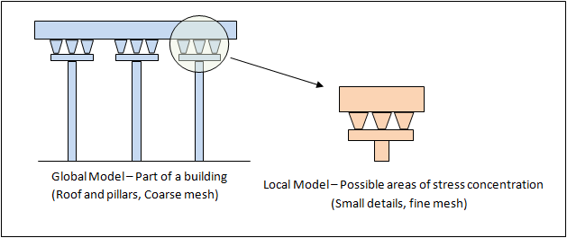
Figure 1. Application of Global-Local Analysis
In Figure 1, an example building is illustrated wherein sections containing the pillar-roof joint are modeled as separate submodels with a refined mesh. The finer mesh allows for better accuracy at regions with high stress concentrations. Using the Global-Local Analysis capability, the results from the coarser global model are interpolated and applied to the finer mesh of the local model at the cut surface. This allows for the local model to be driven by the results of the global model.
One Step Submodeling
The global-local modeling functionality is realized with the help of the subcase specific modeling feature and the subcase selector entry GLOBSUB. This entry is defined in the subcase which contains the local model definition.
GLOBSUB Subcase Information Entry
The full model consists of several sections with areas of high stress concentration or regions of interest which require a higher accuracy. In such cases, the entire model can be solved with a coarser mesh and in each local subcase defining the submodel of interest, the global structure can be referenced using the GLOBSUB entry. The set of grids within the local structure at the cut surface of displacement should be specified.
Format
GLOBSUB, SUBID, SID
Example
$ Subcase Information Section
SUBCASE 1
$ Submodel specific SPCs and LOADs can be defined here.
SUBMODEL, 11
SUBCASE 2
$ Submodel specific SPCs and LOADs can be defined here.
SUBMODEL, 12
GLOBSUB, 1, 15
BEGIN BULK
SET, 11, ELEM     $ defines the global structure, for example, the full building
		  $ in Figure 2
SET, 12, ELEM     $ defines the local structure, for example, the pillar-roof
		  $ joint in Figure 2
SET, 15, GRID     $ defines the cut surface, for example, the interface grids of
		  $ the pillar-roof joint in Figure 2 at which the displacements are                  $ interpolated.
. . .
Save and Restart
ASSIGN, SAVEDISP, <Filename>ASSIGN, GETDISP, <Filename>Refer to the ASSIGN I/O Options Entry for more information.
Comments
- Solution transfer between local and global substructures uses 2D and 3D elements in the global model to interpolate the displacements and rotations at each GRID location belonging to the cut surface set SID. It is recommended that there are no other elements (beams, rods, or rigids) near the cut surface in the global structure as the solution of these elements will not affect the local model. The cut surface should be selected such that in the global structure there are no GRID’s which are connected only to 1D or rigid elements.
- The solution in the elements, near the cut surface in the local model, may lead to some noise resulting from interpolation from the global substructure and should be discarded from the results. The actual zone of interest (for example, stress concentration) should be separated from the cut surface grids by a minimum of two layers of elements in the local model.
- The cut surface should consist only of grids on the cuts (sections) through the structure. Usually, free edges/surfaces without any loading or support conditions should not be part of the cut surface.
- There is no requirement that the cut surface grids exist only on the boundary of the local model. For shell submodels, it may be beneficial to include all grids in the outer layer of elements, as it will improve the transfer of rotations between subcases.
- When certain loading and/or support conditions of the global submodel remain in the local submodel, it is recommended to represent them as loads that are consistent with the local model. For instance, point loading of the global shell structure should be replaced with the equivalent of distributed loading on the local solid substructure. Alternatively, users could decide not to apply the loading/support conditions to the local submodel. In such cases, the grids in the originally loaded/supported area(s) should be included in the cut surface so that the displacements from the global submodel are interpolated and applied to the local structure. However, this technique may significantly reduce accuracy of the local solution.
- The cut surface may represent single or multiple cuts (sections) through the structure. Multiple cuts should not be closer than the element size of the global model.
- For each grid in the cut surface, OptiStruct selects the nearest elements (shell or solid elements from the global model, based on the center location of each element) and uses a solution from all the grids of these elements to interpolate to the cut surface grid location. When the cut surface contains two disconnected substructures, for example, two almost touching shells, care should be taken that this interpolation will not contain nodes from the other substructure. In such cases, PARAM,GLOBEXPT,0 can be used to reduce the number of elements used for interpolation (it will use only grids located close to centers of the elements in the global model).
- The GLOBSUB entry should always reference the subcase ID of a global subcase that is defined above its corresponding local subcase.
- This functionality is currently only available for Linear Static
Analysis. All optimization types with responses from Linear Static Analysis
are supported.
- SPCFORCE/residual force responses are not supported.
- Topology must lie outside the local part(s) and any design variables affecting the local submodel should also be mapped to the global model.
Two Step Modeling
This approach of submodeling involves two steps, analysis of the global model and the local model.
- Analysis of the global model
- In this stage, the global model is analyzed, and the results are stored in along with model information (nodal coordinates).
- Analysis of the local model
- The results from the global model are imported from .h3d file using ASSIGN,H3DRES.
- The specific subcase in the global model, from which results are to be imported, are specified using IMPORT,SUB.
- A grid set is defined for the nodes in the interface/transfer zone (local side).
- SPCD is
defined on these grid sets with a value = M to
signify the mapping.Note: The mapping displacement enforcement can also be directly through SPC instead of SPC/SPCD combination.
- The mapped enforced displacements on this grid set is calculated and applied internally by OptiStruct through point cloud interpolation.
Input File of the Global Model
SUBCASE 1001
	ANALYSIS STATICS
	LABEL Global
	SPC = 10
	LOAD =20
	DISP (ROTA, H3D) = SET_ID
BEGIN BULK
..
Bulk data of the Global Model
..
ENDDATA
Input file of the Local Model
ASSIGN, H3DRES, 100, global_model.h3d
SUBCASE 2001
	LABEL Local
	ANALYSIS STATICS
	SPC = 200
	LOAD = 400

IMPORT (SUB = 1001) = 100
BEGIN BULK
.
.
SPC, 200, 1000, 123456, 0.0
+, GSET

SPCD, 400, 1000, 123456, M
+, GSET
SET, 1000, GRID, LIST
+, 61040, 61041, 61042, 61043, 61044, 61045, 61046, 61047,
+, 61048, 61049, 61050, 61051, 61052
ENDDATA
Comments
- Currently, only displacement results can be mapped in the two step submodeling process and only .h3d file format is supported.
- By default, only translational displacements are mapped and if rotational displacements are desired, then they must be additionally requested.
- Supported analysis types include Linear and Nonlinear (SMDISP/LGDISP) Static Analysis.