Create E-Lines
Use the Create E-Lines tool to create evaluation lines at component interfaces.
- Define interfaces to be evaluated which has Lines as mandatory input, unless you create an E-Line with the Elem2Elem option.
- Turn off the component(s) that are not applicable for the E-Linecreation and/or deselect them while choosing the appropriate component(s) for creation. Make the display selection ready before entering the workflow.
The Create E-lines tool is used to create E-Lines at the interfaces that shall be evaluated for Squeak and Rattle. Create all E-Lines automatically or switch to Manual mode to create E-Lines one by one with more detailed control.
- Fast Create (Part time Analyst): Create E-Lines between multiple entities (Components or Parts) at once without much manual intervention. Use to create many E-Lines at a time, to get a quick and approximate overview of squeak and rattle risk zones.
- Manual Create (Advanced): Add more control to the creation of E-Lines by selecting the Main and Secondary entity (Component, Part or Element is supported) and gap direction. With these additional options, you can ensure the Z-direction of the E-line coordinate system is aligned with the Gap Direction at realization. Use for detailed analysis to ensure accuracy in results.
- Evaluation Points will not be created at the locations where a projection is not found due to a small search tolerance.
- Where and how E-Lines will be created is dependent on Search Tolerance and Spacing.

Fast Create E-Lines
Create E-Lines between multiple components at once without much manual intervention.
Use to create many E-Lines at a time and to get a quick and approximate overview of squeak and rattle risk zones.
-
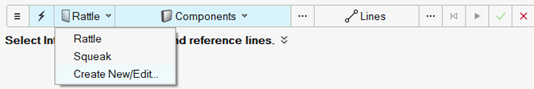
From the Setup group, select the Create
E-Line tool.
Figure 4.
 The guide bar opens.
 - Optional:
From the guide bar, click
 to open edit E-line definition
parameters under the Options menu.
to open edit E-line definition
parameters under the Options menu.
-
Click
 .
Here you have an option to create the E-Line first and then Realize them in next step or realize them directly. At Realization the physical FE-entities representing the E-Lines are created.Unrealized or realized E-Lines are created between the selected components along the selected lines with the specified spacing.
.
Here you have an option to create the E-Line first and then Realize them in next step or realize them directly. At Realization the physical FE-entities representing the E-Lines are created.Unrealized or realized E-Lines are created between the selected components along the selected lines with the specified spacing.
Manually Create E-lines
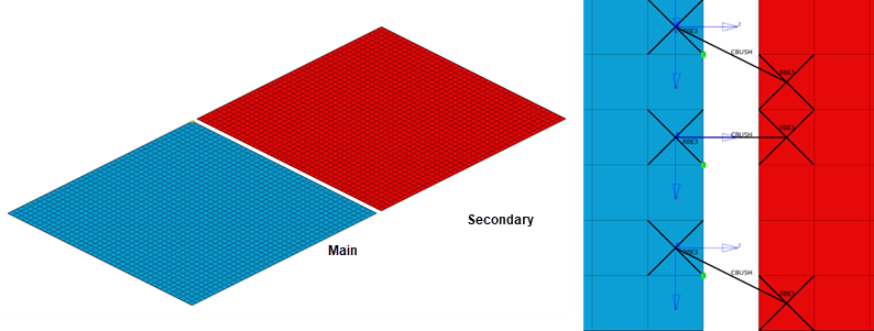
Add more control to the creation of E-Lines by selecting Main and Secondary entity (Component or Element) and gap direction.
-
From the Setup group, select the Create
E-Line tool.
Figure 5.The guide bar opens.
-
Deactivate
 to open Manual mode.
- Optional:
Click to open edit E-line definition parameters under the
Options menu.
-
Click
Tip:
- All E-Lines can be edited at a later stage (see Manage and Review E-lines). For a potential process speed-up, you can create all lines in fast mode and edit them later.
- To create a Single Point E-Line, select an element as Main and another as Secondary. This is used to create flexible attachments such as clips/snaps and diagonal E-Lines to track opening distortion.
Unrealized or realized E-Lines are created between the selected components along the selected lines with the specified spacing.
Create E-Lines Options
There are several options that can be defined via the options menu, these include E-Line and definition of Contact type based on material property.
General E-Line Properties
- Spacing
- Defines the spacing between the E-point placements along the created E-Lines.
- Search Distance
- Defines the tolerance or search distance between interface components/parts.
- Gap Direction
- Realization Projection direction.
- Normal to Main
- Z direction will be perpendicular or Normal to Main
component.Figure 6.

- In Plane to Main
- Z direction will be In Plane to Main component. Figure 7.
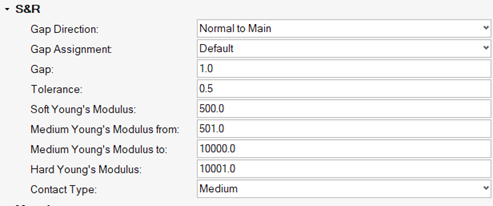
- Gap Assignment
- Defines which method to use to assign Gap and Tolerance values to E-Lines. The assigned gap and tolerance values can be reviewed in E-Line Review Table.
-
- Default
- Predefined template values are assigned.
- From DTS File
- Values from imported DTS file are assigned (default, if DTS file was imported).
- From FE-model
- Gap value is determined based on the distance between two
components in the projected direction.
- Calculated Gap
- Distance between two components in the
projection direction, averaged along the E-lineCalculated Gap = (Thickness Component 1 – Thickness Component 2)/2Figure 8.

- Gap
- Gap value for the interface in the specified gap direction. Defined based on the Gap assignment method.
- Tolerance
- Design tolerance for gap in the specified gap direction. Defined based on the Gap Assignment method.
Rattle Specific Properties
- Contact Types
- Contact types based on Young's Modulus value.
- Soft/Medium/Hard Young Modulus
- Threshold values for definition of Contact type.
Squeak Specific Properties
- (Impulse Rate)-1
- Inverse of Impulse Rate range is a measure of the material pair compatibility. This is defined based on the material mapping and only applies to Squeak lines.
- Main Materials
- Mapped Material from Stick-Slip testing for main component in the E-Line.
- Secondary Material
- Mapped Material from Stick-Slip testing for secondary component in the E-Line.
Material Property
- Contact Types
- Defined Contact type based on Young's Modulus value.
Advanced
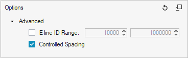
- E-line ID Range
- Define an ID Range for created E-Lines and all entities belonging to them.
- Controlled Spacing
- Define a limit on the spacing to avoid error in solver and numerical issues.