Import Array Layout from Antenna Magus File (*.xml)
This option imports the finite antenna array from an Antenna Magus file (.xml).
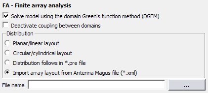
Figure 1. The FA - Finite array analysis dialog, with Import array layout from Antenna Magus (*.xml) selected.
Parameters:
- File name
- The file name of the Antenna Magus file from which the antenna array is to be imported.