Attach a Bushing to the Model
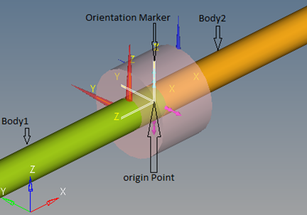
This section describes how you attach a bushing to a model.

Figure 1.
View new features for HyperWorks 2022.
Learn the basics and discover the workspace.
Discover HyperWorks functionality with interactive tutorials.
Start HyperWorks and configure the applications.
Create, open, import, and save models.
Set up sessions and create report templates.
Solver interfaces supported in HyperWorks.
A solver interface is made up of a template and a FE-input reader.
Create and edit 2D parametric sketch geometry.
Create, edit, and cleanup geometry.
FE geometry is topology on top of mesh, meaning CAD and mesh exist as a single entity. The purpose of FE geometry is to add vertices, edges, surfaces, and solids on FE models which have no CAD geometry.
Different types of mesh you can create in HyperWorks.
Create and edit 0D, 1D, 2D, and 3D elements.
Create, organize and manage parts and subsystems.
HyperMesh composites modeling.
Create connections between parts of your model.
Rapidly change the shape of the FE mesh without severely sacrificing the mesh quality.
Create a reduced ordered model to facilitate optimization at the concept phase.
Workflow to support topology optimization model build and setup.
Multi-disciplinary design exploration and optimization tools.
Validate the model built before running solver analysis.
Tools used for crash and safety analysis.
Airbag solutions offer airbag folder utilities and exports a resulting airbag in a Radioss deck.
Essential utility tools developed using HyperWorks-Tcl.
Import an aeroelastic finite element model with Nastran Bulk Data format.
Framework to plug certification methods to assess margin of safety from the model and result information.
Streamline the creation of properties and 1D stiffener mesh using the info read from Marine CAD tools.
Create evaluation lines, evaluate them, and optimize the interfaces to eliminate squeak and rattle issues.
Explore the GeoD user interface.
Panels contains pre-processing and post-processing tools.
Results data can be post-processed using both HyperMesh and HyperView.
HyperGraph is a data analysis and plotting tool with interfaces to many file formats.
MotionView is a general pre-processor for Multibody Dynamics.
MotionView is a general pre-processor for Multi-body Dynamics.
The Model Browser allows you to view the MotionView model structure while providing display and editing control of entities.
The MotionView ribbons allows you to quickly access tools and standard functions, and is located along the top of MotionView.
MotionView supports the importing of several types of CAD and FE formats.
MotionView has many pre-processing and post-processing capabilities with regards to flexible bodies, or flexbodies, for multi-body dynamics models.
From the Preferences dialog, you can access various MotionView options for your model.
Explore the various vehicle modeling tools.
The AutoRider models the mass and inertia of a human body and includes graphics for the human body.
The AutoBush is a bushing model that is designed to easily simulate bushings used in ground vehicles. The AutoBush entity reads bushing stiffness (force-displacement) and damping (force-velocity) data from a file written in the TeimOrbit format.
This section provides information about using the Altair Bushing Model, also known as AutoBushFD, with MotionView. The Altair Bushing Model is a sophisticated model that you can use to simulate the behavior of bushings in vehicle dynamics, durability and NVH simulations.
The Model Identification Tool (MotionView) is a utility in HyperGraph that you use to fit experimental data to various bushing models. The MotionView generates a General Bushing System file, .gbs file, which defines the bushing properties.
You can add an Altair Bushing Model, also known as AutoBushFD, a frequency-dependent bushing, to your MotionView model using the Add Auto Entity tool in MotionView.
This section describes how you attach a bushing to a model.
The Properties window includes five tabs that you can use to define the properties of your bushing.
In addition to adding a single bushing to your project, you can also add a pair of bushings such as AutoBushFD pair. When you add a pair, MotionView automatically reflects modifications you make on the left bushing of the pair to the right bushing, unless you choose otherwise. MotionView assumes bilateral symmetry about the global X-Z plane.
The AutoDamper entity is a force-velocity model designed to easily simulate a shock absorber used in ground vehicles. The AutoDamper entity reads force-velocity data from a file written in the TeimOrbit format.
Reference material for the HyperWorks Desktop scripting interface which is a set of Tcl/Tk commands.
Reference materials for the MotionView MDL Language, Tire Modeling, and the MDL Library.
Reference material detailing command statements, model statements, functions and the Subroutine Interface available in MotionSolve.
Reference material for Templex (a general purpose text and numeric processor) and additional mathematical functions and operators.
Reference materials for the MotionView Python Language.
MediaView plays video files, displays static images, tracks objects, and measures distances.
TableView creates an Excel-like spreadsheet in HyperWorks.
TextView math scripts reference vector data from HyperGraph windows to automate data processing and data summary.
Create, define, and export reports.
MotionView is a general pre-processor for Multibody Dynamics.
Explore the various vehicle modeling tools.
This section provides information about using the Altair Bushing Model, also known as AutoBushFD, with MotionView. The Altair Bushing Model is a sophisticated model that you can use to simulate the behavior of bushings in vehicle dynamics, durability and NVH simulations.
This section describes how you attach a bushing to a model.
This section describes how you attach a bushing to a model.

© 2022 Altair Engineering, Inc. All Rights Reserved.