Spot Weld Fatigue Analysis
Allows for the study of fatigue performance of spot welds in structures.

Figure 1. Spot Weld Fatigue
The length of the spot weld is determined by the attached shell thicknesses. If T1 and T2 are the thicknesses of the two shells, then the length of the spot weld element, L is equal to (T1+T2)/2.
Implementation
The simplified representation of a spot weld is used in OptiStruct to model the fatigue behavior at the weld.
A single weldment may contain a number of sections welded together with welds of different types. However, in this section you only look at analyzing the sections that contain spot welds. Refer to Seam Weld Fatigue Analysis for details about other weld types.
Simplified Spot Weld Representation
A spot weld is represented as a CBAR, CBEAM, CWELD, or CHEXA elements connected to two sheets of shell elements (PSHELL). The CWELD and CBEAM elements are equivalent to a CBAR element internally. The CHEXA element grid point forces are resolved as beam forces at the geometric centers of each face and then they are considered similar to other 1D elements for fatigue calculations.
Spot Weld Fatigue

Figure 2. Spot Weld Fatigue Locations
The following sections illustrates how stresses and subsequently damage are calculated at each of the three locations shown in Figure 3.
Sheet Location (1 or 2)
At sheet location 1 or 2, damage is calculated at the point where the weld is attached to the sheet/shell.
The sheet location 1 is identified by the end A (grid GA) of the nugget (for 1D element nugget) and the face corresponding to the lowest ID’s of the nugget (for CHEXA element nugget). For the structure of CHEXA nugget, refer to Fatigue Input/Output.
The sheet location 2 is identified by the end B (grid GB) of the nugget (for 1D element nugget) and the face corresponding to the highest ID’s of the nugget (for CHEXA element nugget). For the structure of CHEXA nugget, refer to Fatigue Input/Output.

Figure 3. Forces and Moments of Interest at the Sheet Locations
for
- Diameter of the weld element
- Thickness of the sheet under consideration for damage calculation
- Calculated as
The equivalent radial stresses are calculated at intervals of (Default =18 degrees). The value of can be modified by varying the NANGLE field on FATPARM Bulk Data. Subsequently, Rainflow cycle counting is used to calculate fatigue life and damage at each angle (). The worst damage value is then picked for output. A similar approach is conducted for the other sheet.
Nugget Location

Figure 4. Forces and Moments of Interest at the Nugget Cross-Section
for
is the diameter of the weld element.
is the thickness of the sheet under consideration for damage calculation.
The stresses are calculated at intervals of (Default =18 degrees). The value of can be modified by varying the NANGLE field on FATPARM Bulk Data. The equivalent maximum absolute principal stresses are calculated for each from and . These stresses are used for subsequent fatigue analysis. Rainflow cycle counting is used to calculate fatigue life and damage at each angle (). The worst damage value is then picked for output. A similar approach is conducted for the other sheet.
Fatigue Input/Output
Fatigue input for Spot Weld Fatigue Analysis can be divided into the following categories:
Fatigue Element Identification
- The FATDEF Bulk and Subcase entries can be used to identify the elements for which fatigue analysis should be performed. For spot weld fatigue, the PWELD, PBAR, PBEAM, PBARL, PBEAML, and PSOLID continuation lines are available for the definition of the spot weld elements via the PTYPE continuation. Additionally, the ELSET field also supports the CBAR, CWELD, CBEAM, CHEXA entries. The sheets can be defined using the PSHELL continuation line.
- The FATDEF Bulk Data Entry also provides the corresponding PFATSPW Bulk Data Entry references for each spot weld element to define the spot weld fatigue properties.
- If PWELD references are used, then the TYPE field on the PWELD entry should be set to SPOT for spot weld fatigue.
- The DTAB continuation line on the PWELD entry can be used to define the weld element diameter as a function of the minimum shell thickness.
- CHEXA elements
can be used to define the weld element for Spot
Weld Fatigue Analysis. In such cases, the grid
point forces are resolved into corresponding
forces and moments at the face centers of the
opposing faces connected to the shells. The faces
of the CHEXA element attached
to the sheets should always consist of grid points
in the following order. For more
information on the element and the grinding
number, refer to the CHEXA Bulk Data
Entry.

Figure 5. Faces of the CHEXA that Should be Used as Connection Faces with Shells for Spot Weld Fatigue
Additionally, the default weld element diameter of the CHEXA element for spot weld fatigue is equal to two times the smallest distance from the attachment face centroid to the edges.
Fatigue Parameters
- The FATPARM Bulk Data and Subcase Entries can be used to specify fatigue parameters for the Spot Weld Fatigue Analysis.
- The SPWLD continuation line on the FATPARM entry allows you to input the spot weld fatigue method and identify various parameters.
- The PFATSPW Bulk Data Entry allows the definition of some properties for Spot Weld Fatigue Analysis.
Fatigue Material
- The MATFAT Bulk Data Entry can be used to specify the material properties for Spot Weld Fatigue Analysis.
- The SPWLD continuation line allows you to specify mean stress sensitivity value, and separate SN curve attributes for sheet 1, sheet 2, and the nugget.
Fatigue Loads
- Similar to regular fatigue analysis, the FATLOAD, FATSEQ, and FATEVNT entries can be used to define loading sequences.
Optimization
- The weld element diameter (D on PWELD entry) can be used as a design variable in optimization runs using the DVPREL1/DVPREL2 Bulk Data Entries.
- The ATTB field on the DRESP1 entry can be set to SPWLD to activate spot weld fatigue optimization.
Output
Output for Spot Weld Fatigue Analysis is provided similar to regular Fatigue Analysis results. Damage and Life results for the sheet 1, sheet 2, and nugget are available in the H3D file via the Spot Weld Damage(s) and Spot Weld Life(s) result types in HyperView. The damage calculation location can be set in OptiStruct via the SPTFAIL=SHEET, NUGGET, or ALL options on the PFATSPW Bulk Data Entry. Additionally, you can choose to only display the worst damage out of the three damage locations (sheet 1, sheet 2, or nugget) by choosing the Damage(s) result type.
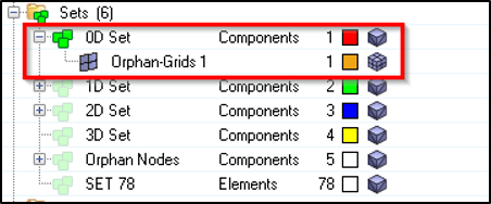
Figure 6. Activating the Orphan Grids Display in HyperView
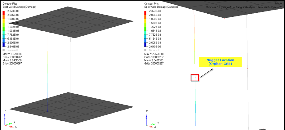
Figure 7. Select and View Results for Spot Weld Damage at the Nugget Location
You can similarly choose to view results at the sheet locations for Spot Weld Damage and Life.