Solder Fatigue Analysis
Solder fatigue is available to analyze and predict fatigue damage of the solder joint between a component and the base Printed Circuit Board (PCB).
- Damage due to mismatch of local thermal expansion coefficients.
- Leadless solder joint
- Ball Grid Array (BGA) solder joint
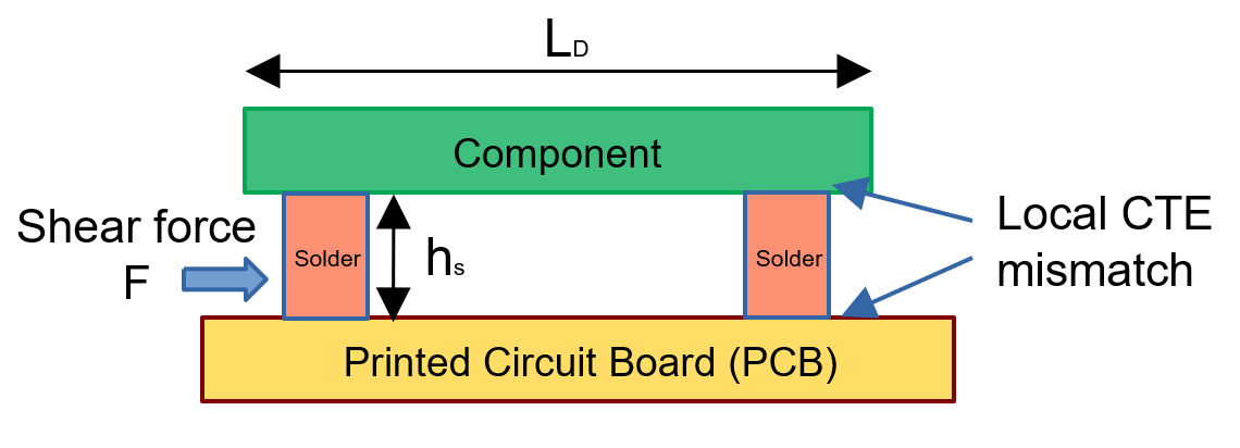
Figure 1. Solder Joint
Fatigue damage due to local thermal expansion coefficient mismatch is assessed. The thermal expansion coefficient field (A) on the MAT1 Bulk Data Entry is mandatory.
- Component length (PKGLEN field on the FATSDR entry).
- Coefficient of thermal expansion (CTE) (A field on the MAT1 entry).
- Solder joint height. (PKGTHK field on the FATSDR entry).
- Difference between thermal expansion coefficients of the PCB and the component soldered onto the board.
- Input temperature.
- Difference between temperatures of the PCB and the component soldered onto the board.
- Empirical model constant for solder fatigue (specified using the C4GAMMA field on the PFATSDR entry). It is equal to for leadless joint type. For BGA type, you can define the empirical model constant.
- Shear force.
- Cross-section area.
- Creep energy density for failure defined on the field of the MATFAT entry.
The default value is 0.0019. If a user defines a value for , the value must be based on the stress unit in MATFAT. The default value for is based on MPa unit. If user-defined stress unit is not MPa in MATFAT, OptiStruct applies a conversion factor to the default value to get a correct value.
Correct default = default x factor that converts MATFAT stress unit to MPa.
Input
Supported solder joint input types for fatigue analysis.
Leadless Solder Joint
The Leadless solder joint is activated by setting the SDRTYP field to XLEAD on the FATSDR entry. The joint is modeled with solid elements. Similarly, the Component/Package and the PCB are idealized with solid elements.
The Element SET ID which defines the Component Package should be defined with the SIDPKG field on the FATSDR entry.
The Element SET ID which defines the PCB should be defined on the SIDPCB field on the FATSDR entry.
Only two SDRis should be specified on the SOLDER continuation line of the FATSDR entry.
Only two Solder joints per package/component are allowed. Multiple FATSDR entries are allowed on a single FATDEF entry.
The FATEVNT entry should only contain a single FATLOAD reference.
Loading should be a static load with Thermal Expansion Coefficient defined.
The input temperature should be the same between the Package and the PCB.
If DIM continuation line on FATSDR is not defined, OptiStruct will attempt to measure it based on the Finite Element mesh.
Ball Grid Array (BGA) Solder Joint
The BGA solder joint is activated by setting the SDRTYP field to BGA on the FATSDR entry. The joint is modeled with solid elements.
The Element SET ID which defines the Component Package should be defined with the SIDPKG field on the FATSDR entry.
The Element SET ID which defines the PCB should be defined with the SIDPCB field on the FATSDR entry.
A single SDRi is allowed on the SOLDER continuation line of the FATSDR entry.
Multiple solder joints per package/component are allowed.
The FATEVNT entry should only contain a single FATLOAD reference.
Loading should be a static load with Thermal Expansion Coefficient defined.
The input temperature should be the same between the Package and the PCB.
If DIM continuation line on FATSDR is not defined, OptiStruct will attempt to measure it based on the Finite Element mesh. For a BGA joint, unless a single solder SET is defined, it is recommended not to define PKGLEN on FATSDR. PKGLEN is assumed to be the distance between the centroid of the package and the solder.
In order to use the method, DIFFCTE must be chosen in the method field following a flag SOLDER in FATPARM.
Output
Supported solder joint output types for fatigue analysis.
General fatigue output for Damage and Life are supported.
Damage due to Creep Deformation of Solder Joint
The approach assumes that solder joint failure is caused by creep deformation of solder joints. Damage of the solder joints can be calculated using either creep strain or creep strain energy density.
Damage Calculation using Creep Strain
- Accumulated strain of a stabilized cycle.
- Inverse of creep ductility.
- Exponent.
The value of is -1 and set as a default value in OptiStruct.
In order to use the method, select SYEDEPS on the METHOD field following the flag SOLDER in FATPARM.
Damage Calculation using Creep Energy Density
- Use the following equation to
calculate life of a solder joint.
(5) Where,- Accumulated creep energy density of a stabilized cycle.
- Creep energy density for failure.
- Exponent.
The value of is -1 and set as a default value in OptiStruct. The creep energy density is obtained from creep energy of an element divided by the element volume.
It is important to note that unit of creep energy density is same as that of stress. Thus, unit of creep energy density is defined as unit of stress in FATPARM. If you define a value for , the value must be based on stress unit in MATFAT.
The default value for is based on MPa unit. If user-defined stress unit is not in MPa for MATFAT, OptiStruct applies a conversion factor to the default value to get a correct value.
Correct default = default x factor that converts MATFAT stress unit to MPa.
In order to use the method, SYEDW should be chosen on the METHOD field following the flag SOLDER in FATPARM.
- Darveaux 2 used the concept of crack growth to
calculate life of a solder joint.
- Crack
initiation:
(6) - Crack
growth:
(7) - Life:
(8)
Where,- Joint diameter at the interface defined in FATSDR.
- K1, K2, K3, and K4
- Constants.
- Averaged creep energy density.
The 4 constants are dependent on the element size chosen in the FEA model. In order to minimize their dependency on element size, the Volume Averaging Technique is usually recommended which is explained in subsequent sections below. After applying the Volume Averaging Technique, K2 and K4 become element size independent quantities. The range of K2 is usually -1.4 to -1.6 and K4 is usually 0.98 to 1.25. K1 and K4 are still dependent on mesh size and creep material constitutive law. Since the 4 constants are not material constants, they are not defined in MATFAT but defined in PFATSDR. The final crack size, is equivalent to joint diameter at the interface.
Units of the averaged creep energy density is the same as unit of stress. Units for dimension of K1 and K3 should be consistent with those of length and stress in FATPARM. Dimension of K1 is cycles/stressK2. Dimension of K3 is (length/cycle)*(1/stressK4). For example, if length unit and stress unit in FATPARM are mm and MPa, respectively, unit of K1 and K3 must be cycles/MPaK2 and (mm/cycle)*(1/MPaK4), respectively.
In order to use the method, select DARV on the METHOD field following the flag SOLDER on FATPARM. The joint diameter at the interface should be defined on FATSDR. K1 to K4 must be defined on PFATSDR.
- Crack
initiation:
Volume Averaging Technique
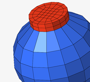
Figure 2. Solder joint
- Averaged strain energy density per cycle of the interface elements.
- Volume of each element in the interface layers.
- Accumulated strain energy density of each element per cycle in the interface layers.
Where, is the accumulated strain of each element per cycle in the interface layers.
The averaged creep strain energy density (SYEDW method and DARV method) and the averaged strain (SYEDEPS method) are used in life calculation.
Report Life/Damage of an Interface Element
- An element that has the most creep strain/creep energy density reports the life/damage calculated using the averaged quantity. Thus, this damage is the maximum damage/the minimum life.
- An element that has the least creep strain/creep energy density reports life/damage calculated using the least creep strain/creep energy density.
- For the rest of elements in the interface layers, logarithmic linear interpolation using the creep strains/creep energy densities of the two elements is performed to estimate their life/damage.
- With the above treatment, you can see the most damaging location of a solder joint while correct maximum damage/minimum life of the solder joint is still reported.
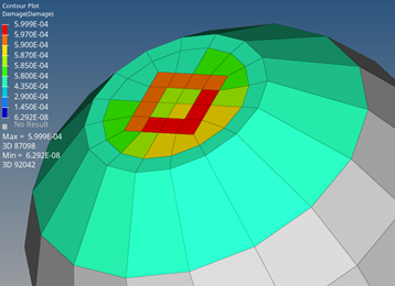
Figure 3. Damage contour that shows the most damaging location of a solder joint
Stablized Cycle
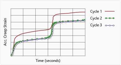
Figure 4.