Comparison

Comparison is used to compare two models using the Model Verification tool.

  1. In the Comparisonブラウザ, right-click and select Check from the コンテキストメニュー.
  2. Select Import Type for Base Model.
    • XML (PLMXML or UDMXML)
    • Assembly (CAD assembly files: UG Assembly, CATProduct, JT Assembly…)
    • CAD (Refer Config / CAD files)
    • FE (Solver deck file)
    • Multiple Assembly (Multiple CAD assembly files)
    • Spot Files (Not applicable)
    • FE Files (direct file selection)
    • Mixed Import (Not applicable)
    • Parts
  3. Select a datatype. Respective data types will be listed.
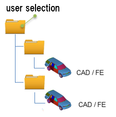
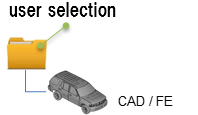
  4. Click the folder icon and navigate to the model to import (Folder/File selections).


    図 1.
  5. Select Import Type for Variant Model.
    • XML (PLMXML or UDMXML)
    • Assembly (CAD assembly files: UG Assembly, CATProduct, JT Assembly…)
    • CAD (Refer Config / CAD section)
    • FE (Nastran, PAM-CRASH, Radioss, Abaqus, OptiStruct, HyperMesh)
    • Multiple Assembly (Multiple CAD assembly files)
    • Spot Files (Not applicable)
    • FE Files (direct file selection)
    • Mixed Import (Not applicable)
    • Parts

    You can select parts directly either from the モデリングウィンドウ or from the Comparisonブラウザ. You must select parts for both the base and the variant. Internally, a quick comparison is executed and results are displayed in the モデリングウィンドウ in addition to the reports.

  6. Select a datatype.
    Respective data types will be listed.
  7. Click the folder icon and navigate to the model to import (Folder/File selections).


    図 2.
  8. In the Tolerance field, enter a value between 0.1 to 5mm to display unmatched entities.
  9. Enter the Threshold[%] value.
    Its min match percentage value, parts that are matching less than this value is treated as Mismatching and parts that are matching above this value will be treated as Matching parts.
    If the match percentage value is greater than the threshold value, then the two entities are shown in report as an overlaid image.
  10. In the Report Path, field navigate to the directory where the reports generated by the Model Verification tool will be stored.
  11. In the Project Name field, enter a name for the project.
  12. In the Slide Number field, enter a starting number of the slides to use in the PowerPoint report.
  13. Select a method for running the model.
    • Choose Interactive to run the model in the same HyperWorks session.
    • Choose Background to launch a new HyperWorks session in batch mode.
  14. The Processes drop-down list becomes active when you select the Background option and it also depends on the processor.
    The Model Verification tool launches as many hmbatch processes selected.
    • Choose Check to execute only the comparison without the report generation.
    • Choose Report to generate only the Reports (Check executed previously).
    • Choose Both to perform the comparison report generation sequentially.
  15. Click Run to execute the function.
  16. Click Stop to stop the operation.
    This closes front and background HyperWorks sessions.
  17. Click View Report to display the Summary PowerPoint report.


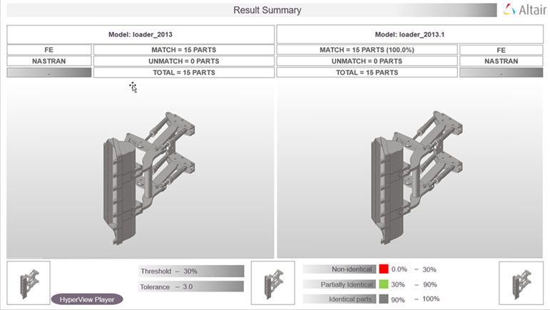
    図 3. PowerPoint Summary . (Stored in Report Path)

    The slide shows the comparison between a source assembly and the target assembly. The left half of the image shows the source assembly and the right half of the image shows the target assembly. In the example illustrated above, the source assembly has a total of 39 parts. The target assembly has a total of 38 parts. The matching parts, between the source and target assemblies, are highlighted in black and the unmatched parts are shown in red.

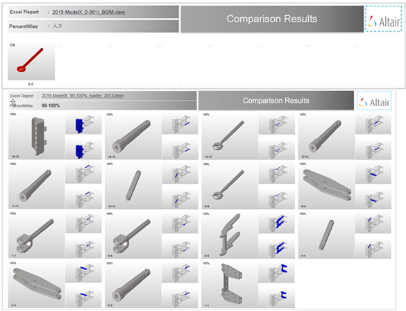
    The second slide shows the matched and unmatched results for individual parts. The number of parts are limited to 40 which matches the Excel report. This limitation can be edited in the configuration.


    図 4. Matched and Unmatched Results. (from 2nd slide of Summary PowerPoint Report)

Output

Overview of the output generated from a Comparison check.

Excel
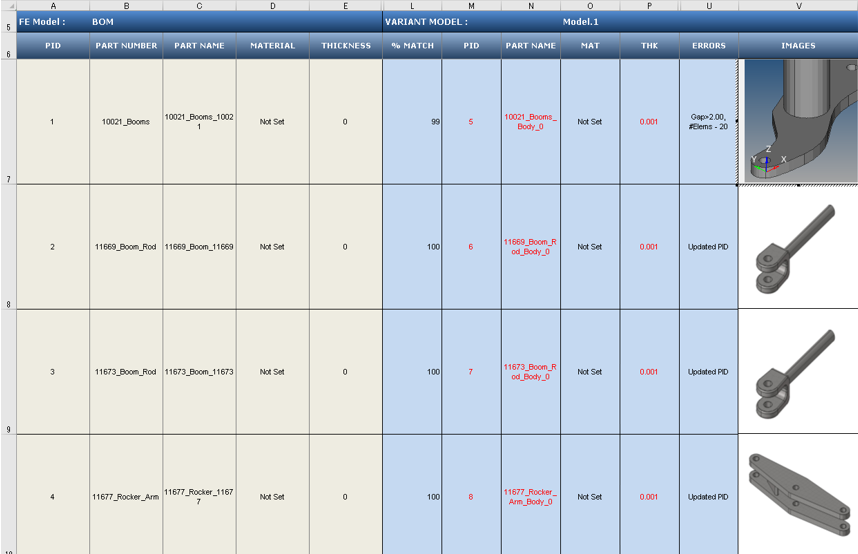
The contents of the Excel report depend on the number of parts/models that are being compared. The report consists of the details of matched and unmatched parts from the assemblies selected for comparison.


図 5.
The information in the Excel reports can be classified into different sections.
Base Model Input
Input information about each of the parts of the CAD model that the tool uses for performing the a comparison check. The Base Model Input is the first assembly shown in the Partブラウザ, and can be cross checked at row 5.
Variant Model Input
Results of the comparison check. The match percentage column shows a part vise match percentage. If the value of match percentage for a part is 0 or less than the threshold percentage, then the part is said to be unmatched with the corresponding part of the other assembly. If the match percentage is above the threshold value, then the parts are considered matching. The error is reported in the error column. Variant model’s Material name or Thickness values are compared against Base model, mismatch values are shown in red text. Variant Model Input increases depending on the number of Variant model found in the Variant Input folder. Variant model name can be cross checked at row 5.
Image Type
Shortcut to the image the part.
  • If the image type is JPG, then this shortcut opens the full sized image for viewing.
  • If the image type is H3D, then the shortcut opens in the part in H3D format in a new HyperWorks window.

Comparison with Browser Selection

Compare CAD vs. CAD models, FE vs. FE models, and CAD vs. FE models with a Comparison check.

In the Comparisonブラウザ, you can select two modules that are required to be compared from the アセンブリブラウザ. Use the Import Models function to import data into the ブラウザ, and then perform the comparison.


図 6. Import Data to Compare
Comments
  • During a Comparison check, the part files may get reloaded several times. Converting all models to the HyperMesh format can improve performance. It is recommended that you perform a No-Offset operation before starting the comparison process by selecting Config > Offset > <action>.
  • During a Comparison check, the part files may get reloaded several times. It is recommended that all models be in HyperMesh format to improve performance. Use the Offset operation before performing a comparison.
  • When generating reports, Excel or PowerPoint reports may open several times. It is recommended that you do not to launch or close any Microsoft Office application or use the keyboard during this operation.
  • Translation or Smetry comparison runs using 1 CPU. A single CPU is automatically utilized, even when you manually set multiple CPUs.
  • If more than one input model is found in the variant folder, a multiple model comparison is activated.
  • The folder structure is to be maintained when organizing variant model files. CAD files must be managed under variant folders, and you must select the variant root folder. If the variant root contains more than one sub folder (variants), a multiple model (variant) comparison is activated.

Troubleshoot Model Verification Comparison Check Problems

Approaches used to troubleshoot Model Verification comparison check problems.

Comparison check results depend on the following Model Verification settings:
  1. The type of CAD files and the corresponding license required to import the CAD files into Model Verification.
  2. The tolerance value specified in the GUI (Thickness/2.0).
  3. Filters specified, such as those in the following list:
    • Connection Name Filter
    • Area Filter
    • CG Filter
    • Match % Filter
  4. Availability of license when using the multiple CPU option. The unit requirement can be calculated using this formula: 40 + ((No. of CPUs * 21) - 21)

Find which filter parts that are excluded from during comparison.
  1. Turn on the debug log in the Configuration panel by selecting Tools > Configuration > Log.
  2. Select log > add.


    図 7.
  3. Restart HyperWorks.
  4. Run the check again.
  5. Check the Tk Console of the stdout files.


    図 8.
  6. Based on the information in the .log file, identify the filters applied on the concern parts/PID.
    Example: 5 vs 109 comparison is ignored due to the centroid distance between these parts are more then value set in the config “cgtolerable-distance” value. In case these two parts need to be compared, increase the “cgtolerable-distance” from 200 to desired value.