.trim file
An ASCII format results file which contains Aeroelastic Analysis results.
File Creation
This file is always created by default for any Aeroelastic Trim analysis run.
File Contents
This file provides detailed information regarding various aeroelastic trim analysis output, like aerodynamic coefficients for trim variables, monitoring information, and so on. Certain results within this file, like aerodynamic element forces and pressures are printed only if corresponding AEROF and APRESSURE I/O Entries are specified.
File Format
The file contains aeroelastic trim analysis solution information for each subcase within the model. Data for all such subcases is printed in the same file, sequentially. For each subcase, multiple sections of data are present. These sections are listed below with examples.

Figure 1.
- Non-Dimensional Stability and Control
Derivative Coefficients:

Figure 2.These coefficients provide trim variable configuration information for the aircraft for surfaces for rigid and elastic cases. These coefficients can be used to compare different configurations of the aircraft and to perform 6 dof simulations.
The non-dimensional coefficients are output as force coefficients (CX, CY, CZ) and moment coefficients (CMX, CMY, CMZ), for each rigid body motion listed on the AESTAT entry and the control surface listed on the AESURF entry.
The stability derivative coefficients printed in this section are non-dimensional since the dimensional force and moment stability derivatives are:- For Force Coefficients: Normalized by the product of dynamic pressure and the reference area of the vehicle.
- For Moment Coefficients: Normalized by the product of dynamic pressure, the reference area, and the arm length. The arm length for CMX and CMZ are normalized by the is the reference span (REFB on AEROS) and arm length for CMY is normalized by the reference chord (REFC on AEROS).
- Transformed to the aerodynamic reference point from the support locationat the origin of RCSID coordinate system. The RCSID system is also referred to as the Body Coordinate system or the reference coordinate system (refer to Coordinate Systems in the User Guide for more information). Normalized by considering the reference chord and span distances.
- RIGID
- Rigid implies that the coefficients are calculated for a rigid analysis. Where the elastic deformation of the structure is ignored for aerodynamic loading.
- SPLINED
- Coefficients calculated on the structural mesh based on the splined configuration. Splines are the connection between the structural and aerodynamic meshes.
- UNSPLINED
- Coefficients are calculated based on the unsplined configurationaerodynamic mesh. If the coefficients are different between the splined and unsplined configurations, then this may indicate that the quality of the spline interpolations is low.
- ELASTIC
- Elastic implies that the coefficients are calculated for a trim analysis wherein the elastic deformation of the structure is considered as a factor for changes in aerodynamic loading.
- RESTRAINED
- For trim analysis, the SUPORT degrees of freedom are considered as SPCs. The coefficients in the restrained configuration are calculated after zeroing out the displacements of these SUPORT degrees of freedom.
- UNRESTRAINED
- The coefficients in the unrestrained configuration are calculated without zeroing out the SUPORT degrees of freedom. Instead extra equations are used to eliminate the singularities associated with these released degrees of freedom.
- Non-dimensional Hinge Moment Derivative Coefficients:
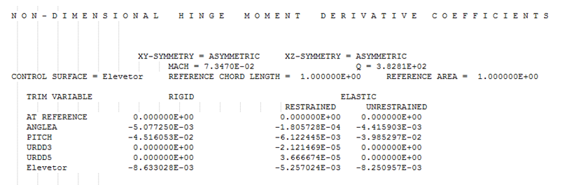
Figure 3. Provides trim variable coefficient information for control surfaces for rigid and elastic casesThe section above contains the hinge moment derivatives for control surfaces. The control surfaces are defined on the AESURF entry, and the non-dimensional coefficients printed here are:- Normalized by the product of reference area, dynamic pressure, and arm length (refer to the section above for more information of the arm length used)
Every control surface contains a hinge, and rotation about this hinge is used to control the configuration of the aircraft. As an example, consider that the Elevator listed in the table above will exhibit a moment of -8.63302E-03 for a rotation of 1.0 radian about the hinge axis and ANGLEA=PITCH=URDD3=URDD5=0.0.
- Intermediate Matrix: The coefficients listed here are dependent on the rigid body modes of the structure.
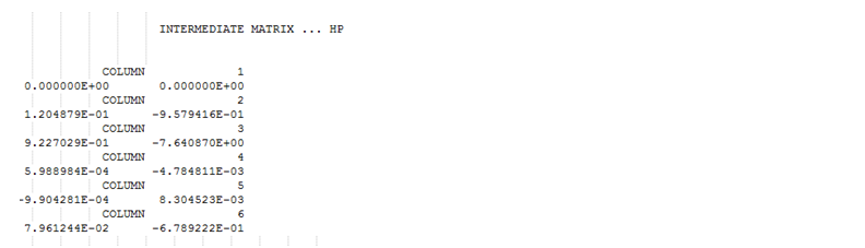
Figure 4. Some Internal Inertia Relief Information - Aeroelastic TRIM variable data, status, and
corresponding bounds.
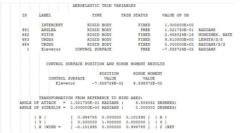
Figure 5. Includes Control Surface InformationThe first part of the above table provides the trim variable data, status and, type. The trim variable data also includes the control surfaces. The second part of the table contains information regarding the transformation matrix from the reference to the wind axes. The wind coordinate system can differ from the reference when, say, a new angle of attack creates a wind velocity angle change. (refer to Coordinate Systems in the User Guide for more information).
- Structural mesh:
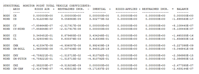
Figure 6. Monitor Point Total Vehicle CoefficientsThe monitor point information displayed in Figure 6 is not controlled by MONPNTi entries. The table illustrates the summation of forces and moments in each direction and coordinate system (BODY/WIND).- BODY
- Indicates the body reference coordinate system.
- WIND
- Indicates the Wind coordinate system (refer to the section above for definition of the Wind coordinate system).
- CX, CY, CZ, CMX, CMY, and CMZ
- The forces and moments coefficients in the BODY coordinate system.
- CD
- The drag in the new Wind X-Axis. CY is the same as CY of the body RCSID coordinate system.
- CL
- Perpendicular to the fluidair velocity vector (perpendicular to CD).
- RIGID AIR – coefficients
- Indicates the coefficients of force only due to aerodynamics. Forces on the structure due to the trim configuration of the vehicle (does not include applied loads or inertial loads).
- RESTRAINED INCR (column 2 in the table) – coefficients
- Indicates the coefficients of additional incremental aerodynamic forces due to elastic deformation from the initial aerodynamic loads (RIGID AIR) and inertia loads (INERTIAL). This does not include the contribution of applied loads (RIGID APPLIED) to the additional incremental aerodynamic loads.
- INERTIAL – coefficients
- Indicates the coefficients of inertial forces on the structure. Inertial forces are any forces arising due to mass for a particular trim configuration.
- RIGID APPLIED – coefficients
- Indicates the coefficients of user input/external applied forces. These are any loads specified as forces, moments, etc. in the subcase definition.
- RESTRAINED INCR (column 6 in the table)
- Coefficients (this is the repeated column after RIGID APPLIED)
- Aerodynamic mesh:
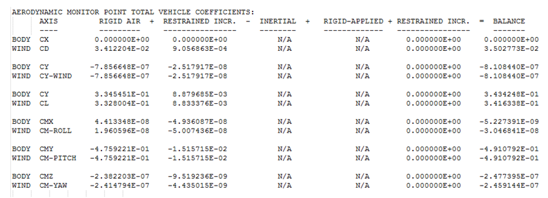
Figure 7. Monitor Point Total Vehicle CoefficientsThe Monitor point information displayed in Figure 6 is not controlled by MONPNTi entries. The table illustrates the summation of forces and moments in each direction and coordinate system (BODY/WIND).
For the aerodynamic mesh, the items listed below are interpreted the same as they are for the structural mesh table in the previous section.- BODY
- Indicates the body reference coordinate system.
- WIND
- Indicates the Wind coordinate system (see section above for definition of the Wind coordinate system).
- CX, CY, CZ, CMX, CMY, and CMZ
- Forces and moments coefficients in the BODY coordinate system.
- CD
- Drag in the new Wind X-Axis.
- CY
- The same as CY of the body coordinate system.
- CL
- Perpendicular to the fluidair velocity vector (perpendicular to CD).
- RIGID AIR – coefficients
- Indicates the coefficients of force only due to aerodynamics. Forces due to the trim configuration of the vehicle (does not include applied loads or inertial loads).
- RESTRAINED INCR (column 2 in the table) – coefficients
- Indicates the coefficients of additional incremental aerodynamic forces due to elastic deformation from the initial aerodynamic loads (RIGID AIR) and inertia loads (INERTIAL). This does not include the contribution of applied loads (RIGID APPLIED) to the additional incremental aerodynamic loads.
- INERTIAL and RIGID APPLIED
- N/A because they are not defined in the aero mesh.coefficients
- RESTRAINED INCR (column 6 in the table) – coefficients
- (this is the repeated column after RIGID APPLIED)
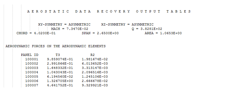
Figure 8. Aerodynamic Force Output (controlled by AEROF entry)The following columns are of interest:- PANEL ID
- Identifies the Panel ID for which the Aerodynamic Force is output.
- T3
- This is the direction perpendicular to the panel. The X axis is the same as defined by AEROS (ACSID). After points 1 and 4 (CAERO1 entry) are placed, the perpendicular direction is assumed as Z direction. From X and Z, the Y axis can be calculated.
- R2
- Pitching angle of each panel.
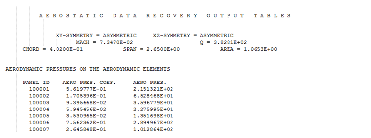
Figure 9. Aerodynamic Pressure Output (controlled by APRESSURE entry)Figure 9 lists the Aerodynamic Moments Output that is controlled by the AEROF entry. The following columns are of interest:- PANEL ID
- Identifies the panel ID for which the Aerodynamic Moment is output.
- AERO PRES. COEF.
- Aerodynamic pressure coefficients.
- AERO PRES.
- Aerodynamic pressures.
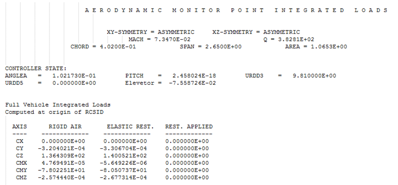
Figure 10. Monitor Point Total Integrated LoadsThis table identifies the full vehicle integrated loads at the origin of RCSID. The coefficients indicated in the descriptions below are sourced from the Structural Mesh – Monitor Points Coefficients table above.
For a more detailed explanation of the terms below, see the corresponding Structural Mesh – Monitor Points Coefficients table description above.- AXIS
- Indicates the force or moment degree of freedom.
- RIGID AIR - loads
- This is calculated as the RIGID AIR coefficient * dynamic pressure * area.
- ELASTIC REST - loads
- Calculated as (RIGID AIR coefficient + RESTRAINED INCR, Column 2, coefficient) * dynamic pressure * area.
- INERTIAL - loads
- Calculated as INERTIAL coefficient * dynamic pressure * area.
- RIGID APPLIED - loads
- This is the actual user input loading.
- REST. APPLIED
- Calculated as (RIGID APPLIED coefficient + RESTRAINED INCR, Column 6, coefficient) * dynamic pressure * area
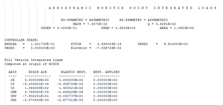
Figure 11. Monitor Point Total Integrated LoadsThis table identifies the full vehicle integrated loads at the origin of RCSID. The coefficients indicated in the descriptions below are sourced from the Aerodynamic Mesh – Monitor Points Coefficients table above.
For a more detailed explanation of the terms below, see the corresponding Structural Mesh – Monitor Points Coefficients table description above.- AXIS
- Indicates the force or moment degree of freedom.
- RIGID AIR - loads
- This is calculated as the RIGID AIR coefficient * dynamic pressure * area.
- ELASTIC REST - loads
- Calculated as (RIGID AIR coefficient + RESTRAINED INCR, column 2, coefficient) * dynamic pressure * area.
- REST. APPLIED
- Calculated as (RIGID APPLIED coefficient + RESTRAINED INCR, column 6, coefficient) * dynamic pressure * area.