Normals Panel
Use the Normals panel to display and reverse the normals of elements or surfaces. The orientation of element normals can also be adjusted. The normal of an element is determined by following the order of nodes of the element using the right-hand rule.
Location: Tools page
For the Abaqus solver interface this panel can be used to adjust or reverse the stacking direction of continuum shells.
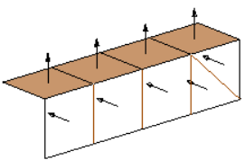
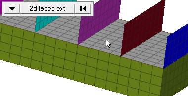
Figure 1. Normals using Vectors. Some elements have been set to transparent mode.
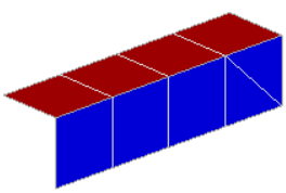
Figure 2. Normals using Colors. Red indicates positive; blue indicates negative.
Elements Subpanel
Use the Elements subpanel to display and reverse the normals of elements. Select elements indirectly by components or directly by elements, or elect to have all of the displayed 2D elements selected automatically. Click display to review the current normal orientation of the selected elements. Optionally, click reverse to flip the normals to the opposite side (reverse the normals).
You can also use the Elements subpanel to adjust element normals. Select elements to adjust, then select an orientation method which determines how element normals are adjusted. When you are finished, click adjust. Optionally, select display adjusted only to only display the elements which have been adjusted in this operation. All elements selected for adjusting must be in a continuous mesh for this operation.
On review, normals are displayed with vectors by default. Alternatively, you can choose to display normals in color mode by switching the toggle from vector display normals to color display normals. Normals pointing in the wrong direction can be spotted easier in bigger meshes when using the color display mode. Red indicates the positive normal direction and blue indicates the opposite side of the element.
In vector mode, specify the size of normals in the size field. If this value is zero, the normal is sized based on the smallest side of the element. If a value other than zero is specified for size, the normal is drawn based on the length specified in model units.
| Option | Action |
|---|---|
| displayed 2D elems/comps/elems | Select elements to
display, adjust, or reverse the normals of.
When you select elems, click the switch to change the
selection mode.
|
| orientation | Select a method for
adjusting element normals.
|
| use feature angle | Specify a feature
angle (mode=4, and a feature_angle is used). For each connected section, the normals are adjusted for all elements in that section to be consistent with the 'dominant normal direction' already existing within that section, with the sections defined based on the specified feature angle. Clear this checkbox to not use a feature angle, and set the mode to 0. |
| vector display normals / color display normals | Choose a method to review normals of elements. Normals can be shown as vectors or by color code. In color mode, red indicates the positive normal direction, while blue indicates the negative direction. |
| size = | Adjust the vector size if vector display normals is selected. If a value greater than zero is specified it shows the normal in that size based on model units. Otherwise, the vector size is equivalent to the smallest size of the element. |
| display adjusted only | Display the normals which have been changed when you click adjust. |
| display | Display the normals of selected elements or surfaces as vectors or in color mode. |
| adjust | Adjust normals based on the orientation method you specified. |
| reverse | Flip all of the normals of the selected elements or surfaces. |
| face angle / individual selection |
|
Surfs Subpanel
Use the Surfs subpanel to display and reverse normals of surfaces. Select surfaces indirectly by components or solids or directly by surfaces, or elect to have all of the displayed surfaces selected automatically. Click display to review the current normal orientation of the selected surfaces. Optionally, click reverse to flip the normals to the opposite side (reverse the normals). After clicking display or reverse, the normals will either be shown as vectors or in color mode, depending on the setting of the vector display normals/color display normals toggle.
Adjust the vector size by entering a value in the size field. The vector will either be drawn in model units based on the value or the vector size will be 10% of the screen if zero is entered.
The minimum set of surfaces required is automatically adjusted to maintain overall consistency of the surface normals, without affecting other surfaces, based on the input surface selection. The minimum set of surfaces is found from all surfaces attached by shared edges. This includes the entire surface shell, not just the adjacent surfaces. This prevents problems that can arise from incorrect or inconsistent orientations.
| Option | Action |
|---|---|
| displayed surfs/comps/surfs/solids | Use the switch to
select surfaces to display or reverse the normals of.
|
| adjust associated FE | Adjust the FE orientation of normals associated with the selected surfaces when reverse is clicked. |
| vector display normals / color display normals | Choose a method to review normals of surfaces. Normals can be shown as vectors or by color code. In color mode, red indicates the positive normal direction, while blue indicates the negative direction. |
| size = | Adjust the vector size if vector display normals is selected. If a value greater than zero is specified it displays the normal in that size based on model units. Otherwise, the vector size is equivalent to 10% of the screen. |
| reverse normals | Flip all of the normals of the selected surfaces. |
Abaqus Additions
Additional functionality in the Normals panel is available for the Abaqus solver interface if entered through the Composites panel of the 2D page. This helps to set up models using continuum shell elements. It applies to elements with the Engineering Solutions configurations penta6, penta 15, hex8 and hexa20.
When display is clicked, the default stack direction is displayed without considering the property assigned to the underlying elements. The review is based on the numbering scheme of the continuum shell element. Click display stack direction to show the stack direction of all of the selected elements considering the setting of the elemental property. Supported are all three isoparametric directions as well as the definition by a system (*ORIENTATION). Normals are either displayed as vectors, or colors when in the color display normals mode (the bottom face shows in blue, and the top face in red).
- by reference element
- The default stacking direction of all selected elements can be adjusted
to a reference element which needs to be selected with the elem
selector. Note: Only works on models with one layer of continuum shell elements.
- by nodes on bottom face
- Selected elements will be adjusted by selecting the nodes on the bottom
face of one element. The stack direction will then point from the bottom
face to the opposite face of the element. For hexahedron elements, two
diagonal nodes or three nodes can be selected; for pentahedron elements
three nodes need to be selected. Note: Only works for multiple layers of elements.
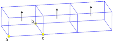
Figure 6. Adjust Normal by Nodes on Bottom Face. Either two nodes a and b, or an additional node c can be selected to define the bottom face for a continuum shell element.
Reverse normal and reverse stack direction return the stacking direction to the opposite.
Adjust normal and both reverse functions affect the element numbering. Applied loads are automatically corrected upon adjustment to apply to the correct face of the element.