Quality Index Cleanup Tools Secondary Panel
Use the Quality Index Cleanup Tools secondary panel to access tools that assist you in manually relocating nodes and optimizing element topology.
Location: Accessed by clicking cleanup tools from the Quality Index panel
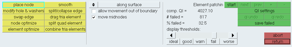
Figure 1.
Place Node Tool
| Option | Action |
|---|---|
| along surface / normal to surface | Choose which direction
the node will move.
|
| allow movement out of boundary | Move the nodes past
the edges of a mesh boundary.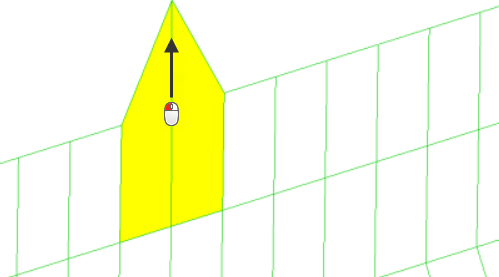 Figure 4. Movement Along Surface, Allowing Movement Out of Boundary Note: Available when along surface is
selected.
|
| move midnodes | Move the midnodes
associated with the node you are moving. Tip: Useful
when working with second order elements.
|
Modify Hole and Washer Tool
| Option | Action |
|---|---|
| radial | Alter the radius of a
hole (and, optionally, the washer). To alter the radius of
the hole, click and drag a node. The element orientation
remains constant, but the hole may become larger or smaller
based on the input. There are additional controls to enable
or disable automatic remeshing when altering the hole
dimensions.
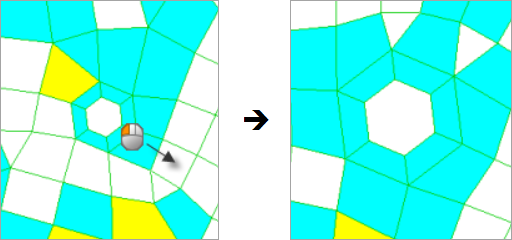 Figure 5. |
| radius: (and edit check box) | Displays the current
radius of the hole that the selected node belongs to. By default
it is a display-only field. If you do not want to click and drag a node, enable the edit checkbox to specify a desired radius. Once you click a node in the desired hole, the radius will change to the specified value. |
| angular | Move the nodes around
the edges of the hole without changing the hole diameter or the
spacing between nodes.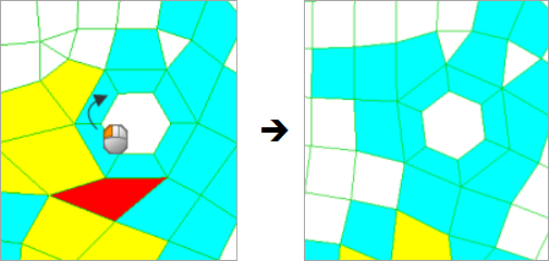 Figure 6. |
| angle: (and edit check box) | Displays the current
angle of the hole that the selected node belongs to, relative to
its original (unmodified) starting position. By default it is a
a display-only field. If you do not want to click and drag a node, enable the edit checkbox to specify a desired angle. Once you click a node in the desired hole, the angle will change to the specified value. |
| radial and angular: | Simultaneously change
the hole's radius and the orientation of nodes around its edge.
Like the angular option, the node spacing remains proportionally
consistent, though actual spacing will be scaled in accordance
with changes in the hole radius.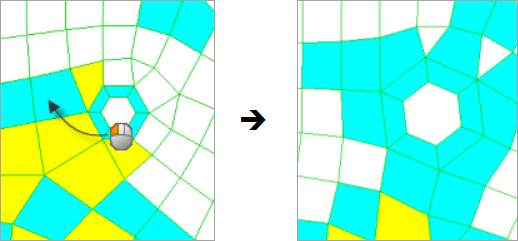 Figure 7. |
| radial and angular: (and edit check boxes) | Displays the current
angle and radius of the hole that the selected node belongs to.
By default they are both a display-only field. If you do not want to click and drag a node, enable both edit checkboxes and specify a desired angle and radius. Once you click a node in the desired hole, the angle and radius will simultaneously change to the specified values. |
| circumferential | Rotate the nodes along
the circumference of the slot without altering the hole's size
or shape/orientation. Note: This option is primarily used on
opening like slots. The capability works on enclosed slots
or holes. It is not designed to work on slots with an
opening.
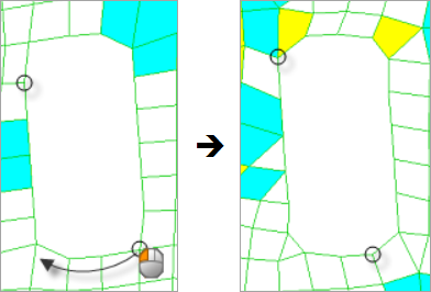 Figure 8. |
| circumferential (and edit check box) | Displays the current
arc length of the hole that the selected node belongs to. By
default it is a display-only field. If you do not want to click and drag a node, enabled the edit checkbox and specify a desired arc length. Once you click a node in the desired hole, the arc length will change to the specified value. |
| link washers | Change the radial or
angular position of nodes, as well as drag and scale the washer
nodes along with them. In order for the link washers option to
work, you must enable the allow to move fixed and shared nodes
checkbox in page 4 of the Quality Index panel.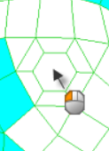 Figure 9. Original Model 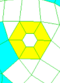 Figure 10. Link Washers Option Disabled 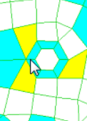 Figure 11. Link Washers Option Enabled |
| retain washer width | Alter the radius of a
hole without changing the width of a washer. Clear this
checkbox to change the radius of the hole and the washer
simultaneously.
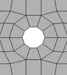 Figure 12. Original Model 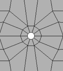 Figure 13. Retain Washer Width Disabled 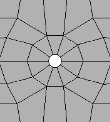 Figure 14. Retain Washer Width Enabled Note: Available for radial and radial &
angular changes, when the link washers checkbox is enabled.
|
| remesh number of layers: | To specify the number of washer layers to automatically remesh after you alter the node position, select this check box. |
Swap Edge Tool
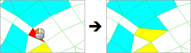
Figure 15.
For a pair of trias, there are two possible positions for their shared edge. For a pair of quads, there are three possible positions. For a quad and a tria, there are six possible positions.
Node Optimize Tool
Use the Node Optimize tool to automatically move a selected node to optimize the overall quality of its surrounding elements. The options along surface, normal to surface, and along and normal to surface work exactly as described for the place node tool. The only difference is that node optimize moves the node automatically, while place node requires you to choose the location manually.
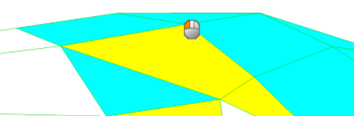
Figure 16. Select Node to Move. The mouse indicates the node that will be moved in each of the following examples.
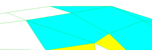
Figure 17. Move Node Along Surface
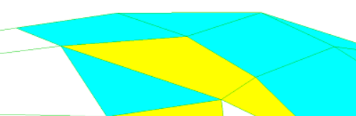
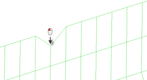
Figure 18. Move Node Normal to Surface
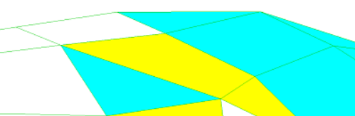
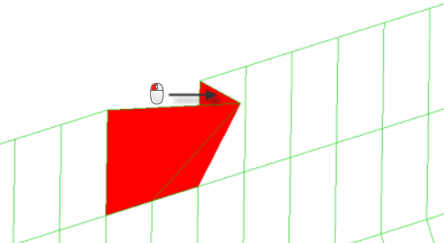
Figure 19. Move Node Along and Normal to Surface
Element Optimize Tool
Use the Element Optimize tool to automatically optimize the shape of the selected element and the elements surrounding it. It is similar to Node Optimize, except that its effects are wider-spread.
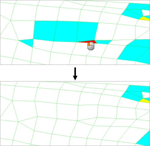
Figure 20.
Smooth Tool
Use the Smooth cleanup tool to improve element quality in a surface-based mesh. This cleanup tool uses one or more algorithms to adjust node positions to moderate sharp variations in size or quality in adjacent elements, and to adjust the position of the free nodes of the selected shell elements to smooth out variations in element quality and size.
- It is used by an element that was not selected.
- It is selected as an anchor node.
- It is attached to an edge, vertex, or meshing fixed point of a surface.
- It is used by a 1D element (whether or not that element is selected).
- It is not attached to a surface, but is on a feature line of the mesh of the selected plate or shell elements.
| Option | Action |
|---|---|
| smooth: elements | Select the element(s) you want to smooth. |
| anchor: nodes | Select an anchor a node (for example, you may use an anchor node at a weld site). |
| mesh algorithm options | Select a smooth
function behavior.
|
Split/Collapse Edge Tool
Use the split/collapse edge cleanup tool to split or collapse the edges of elements in your model.
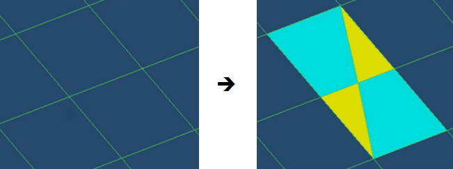
Figure 21.
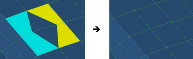
Figure 22.
Drag Tria Element Tool
Use the drag tria element cleanup tool to drag a tria element to a different location in the model, or out of the model completely.
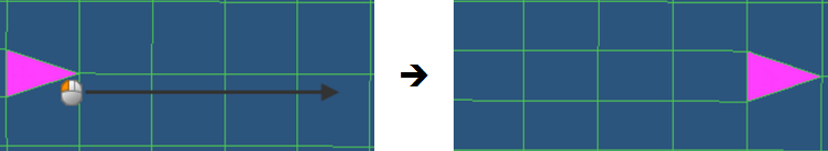
Figure 23.
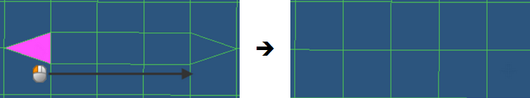
Figure 24. Merge Trias Checkbox Enabled
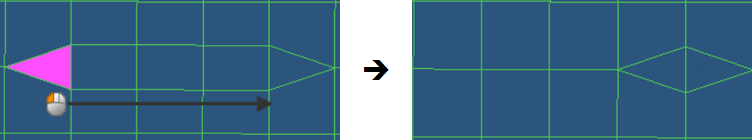
Figure 25. Merge Trias Checkbox Disabled
Split Quad Element Tool
Use the split quad element cleanup tool to split a quad element into two tria elements.
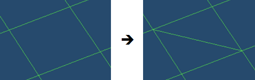
Figure 26.
Combine Tria Elements Tool
Use the combine tria elements cleanup tool to combine two tria elements into one quad element.
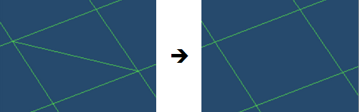
Figure 27.
Patch Checker Tool
Use the Patch Checker to review patches of failed elements, as well as quality results. Each patch contains failed element with layers of elements around it. To increase or decrease the number of layers, click + or - respectively. To see the next or previous patch, click next or prev respectively.
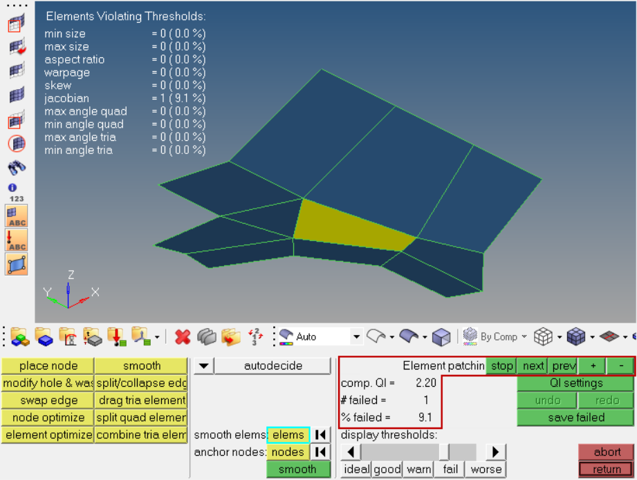
Figure 28.
Command Buttons
| Button | Action |
|---|---|
| QI settings | Return to the Quality Index Panel. |
| Undo | Undo the most recent edit. Multiple levels of undo are available. |
| Redo | Redo the most recently undone edit. Multiple levels of redo are available. |
| Save failed | Save all of the elements deemed failed to memory. Use the extended entity selection menu of any elems selector in another panel to retrieve the list of failed elements and automatically select them. |
| Abort | Discard all changes and return to the Quality Index panel with the mesh unchanged. |
| Return | Keep all changes and return to the Quality Index panel. |