Spotweld Panel
Use the Spotweld panel to create 1D elements to connect different parts.
Location: 1D page
Spotwelds can be created one at a time or in groups using the Using Geom, Using Nodes, or Using Elems subpanels.
Using Geom Subpanel
| Option | Action |
|---|---|
| surfs-surfs / lines-surfs |
|
| all surfs / ind surfs |
|
| surfs selector | Select the independent
surfaces. When using all surf, select two (or more) surfaces between which to create the element(s). |
| element config | Select type of element to create. |
| weld location | Select the nodes or
points where you want to create spotwelds.
|
| property | Assign properties to the spotweld element(s). |
| search tolerance | Specify the tolerance value to use to identify relevant surfaces between which to create the elements at the specified locations. |
| without systems / build systems |
|
| spacing / density |
Note: Available when line-surfs is selected.
|
| offset options | You can either explicitly state the offset distance from each end on the line, or you can use the 1/2 spacing option. The 1/2 spacing option determines the distance between two welds and sets the explicit offset to 1/2 of this distance. |
Using Nodes Subpanel
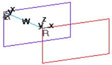
Figure 1. Weld Created using Build Systems
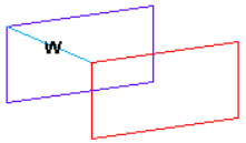
Figure 2. Weld Created using Without Systems
The local coordinate systems are oriented with the y axis located along the direction between the selected nodes.
| Option | Action |
|---|---|
| indep node selector | Select the independent node. |
| dep node selector | Select the dependent
node. Engineering Solutions builds the element after you select the dependent node. |
| element config | Select the type of element to create. |
| move dep node | Move the dependent
node along the surface in which it lies and create a spotweld
normal to the independent surface. If the quality of the
resulting mesh due to the movement of the dependent node is not
acceptable, click reject and select
remesh dep region to remesh the
dependent region. Note: This option remeshes only the dependent
region affected by the movement of the dependent
node.
|
| property | Assign properties to the spotweld element(s). |
| without systems / build systems |
|
Using Elems Subpanel
Use the Using Elems subpanel to create spotwelds and internally remesh the surrounding elements.
If more than two elements are within the search radius, spotweld elements are not created. To create welds in this situation, select a pair of elements at a time.
The local coordinate systems are oriented with the y axis located along the direction between the selected nodes.
| Option | Action |
|---|---|
| all elems / ind elems |
|
| elems selector | Select elements. |
| element config | Select the type of element to create. |
| weld location | Select the nodes or points where you want to create spotwelds. |
| property | Select the property collector to be assigned to the element. |
| search tolerance | Specify the tolerance value to use to identify relevant surfaces between which to create the elements at the specified locations. |
| without systems / build systems |
|
| attach to shell elems | Create 1D connection elements and attach them to neighboring shell elements by internally remeshing the surrounding elements. |
Switch Nodes Subpanel
| Option | Action |
|---|---|
| elems selector | Select the weld elements whose dependent and independent nodes you want to switch. |
Command Buttons
| Option | Action |
|---|---|
| create | Create the spotweld element. |
| reject | Revert the most recent changes. |
| review | Display the selected spotweld elements. |
| switch | Switch the selected elements. |
| return | Exit the panel. |