Accels Panel
Use the Accels (accelerations) panel to create and update concentrated accelerations by applying a load, representing accelerations, nodes, components, sets, surfaces, points, or lines.
Location: Analysis page
Accelerations
Configuration 9 - Acceleration loads allow for an acceleration (length/time2) to be defined on the model.
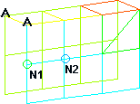
Accelerations are displayed as a vector with the letter A at the tail end in the modeling window.
Create Subpanel
Use the Create subpanel to create accelerations.
| Option | Action | ||
|---|---|---|---|
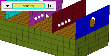
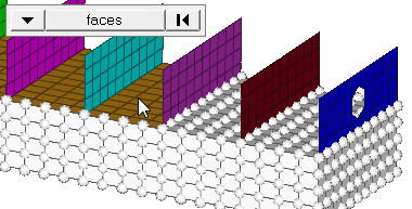
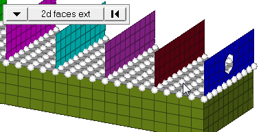
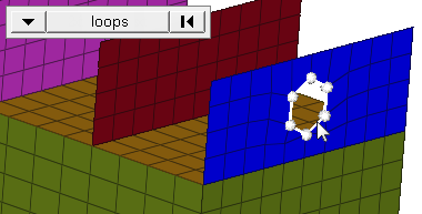
| entity selector | Select entities to which accelerations
should be applied. If accelerations are applied to nodes; this selection
determines how those nodes are selected. Geometric points select the nodes at
which they exist. Comps select all of the nodes contained within the chosen
component. When nodes is selected,
click the switch to change the selection mode.
|
||
| display |
Indicate where in the model to draw the indicator.
Important: Only available when the entity selector is set to comps or
sets.
|
||
| global system/local system | Define an acceleration's direction relative to a local coordinate system or the default global system. | ||
| vector | Select an existing vector entity that defines the direction of the acceleration. | ||
| curve |
Select the acceleration curve.
Important: Only
available when magnitude= is set to curve, vector or curve,
components.
|
||
| magnitude= | Define the value of the load for static use cases and scale factor of a curve for transient or dynamic analysis. | ||
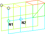
| N1 N2 N3 |
Select two or three nodes on your model to indicate the vector
along which the acceleration should act.
Important: Only available when
magnitude= is set to constant vector or curve, vector.
|
||
| x comp, y comp, z comp |
Change the x, y, and z components of the magnitude.
Important: Only available when magnitude= is set to constant components or
curve, components.
|
||
| xscale= | Change the value to alter the curve’s X scale (for example, time). | ||
| vector direction | Specify the vector along which the acceleration should act. | ||
| relative size/uniform size |
By default, loads are displayed relative to the model
size.
|
||
| label loads | Display the load's text labels in modeling window. | ||
| load types | Select a load type. | ||
| face angle/individual selection |
|
||
| edge angle |
Split edges that belong to a given face. When the edge
angle is 180 degrees, edges are the continuous boundaries of faces. For smaller
values, these same boundary edges are split wherever the angle between segments
exceeds the specified value. A segment is the edge of a single element.
Important: Only available when the entity selector is set to nodes and the
selection mode is set to free edges, free edges ext, edges, or edges
ext.
|
Update Subpanel
Use the Update subpanel to edit and update accelerations.
| Option | Action | ||
|---|---|---|---|
| entity selector | Select entities to which accelerations
should be applied. If accelerations are applied to nodes; this selection
determines how those nodes are selected. Geometric points select the nodes at
which they exist. Comps select all of the nodes contained within the chosen
component. When nodes is selected,
click the switch to change the selection mode.
|
||
| display |
Indicate where in the model to draw the indicator.
Important: Only available when the entity selector is set to comps or
sets.
|
||
| global system/local system | Define an acceleration's direction relative to a local coordinate system or the default global system. | ||
| vector | Select an existing vector entity that defines the direction of the acceleration. | ||
| curve |
Select the acceleration curve.
Important: Only
available when magnitude= is set to curve, vector or curve,
components.
|
||
| magnitude= | Define the value of the load for static use cases and scale factor of a curve for transient or dynamic analysis. | ||
| N1 N2 N3 |
Select two or three nodes on your model to indicate the vector
along which the acceleration should act.
Important: Only available when
magnitude= is set to constant vector or curve, vector.
|
||
| x comp, y comp, z comp |
Change the x, y, and z components of the magnitude.
Important: Only available when magnitude= is set to constant components or
curve, components.
|
||
| xscale= | Change the value to alter the curve’s X scale (for example, time). | ||
| vector direction | Specify the vector along which the acceleration should act. | ||
| relative size/uniform size |
By default, loads are displayed relative to the model
size.
|
||
| label loads | Display the load's text labels in modeling window. | ||
| load types | Select a load type. |
Command Buttons
| Button | Action |
|---|---|
| create | Create an acceleration. |
| update | Update an acceleration. |
| review | Review an acceleration. |
| return | Exit the panel. |