HyperMorph Shapes Panel
Use the HyperMorph Shapes panel to create, save, load, reposition, reflect, convert, smooth, animate, and apply morphing shapes.
Location: Tool page > HyperMorph module
Settings made on one subpanel are not lost if you switch subpanels, but may be lost if you return out of the panel.
Save As Shape Subpanel
Use the Save as Shape subpanel to save a morph as a shape, which can then be applied to meshes and used for optimization. After saving the shape, click undo all to go back to the original state of the model or continue morphing.
| Option | Action |
|---|---|
| as handle perturbations / as node perturbations | Shapes saved as handle perturbations take up less space and can change if the domains and handles for the model are changed. If you edit the domains and handles in a model that has saved shapes or morphs on the undo/redo list, you will be given the option to preserve those shapes as node perturbations. If you click yes, the shapes will retain their original form. If you click no, the shapes will be unchanged internally, but may be appear different due to changes in the influences of the perturbed handles. |
| color | Select a color for the current shape. |
| global system / syst | Shapes must reference a coordinate system which affects both how the shape is applied and how it is written to a data file. When a shape is applied to the model the shape's perturbations are converted into the system's coordinates, scaled, and then converted back into the global system. This allows a shape which references a cylindrical or spherical coordinate system to rotate through an angle when scaled rather than move linearly when applied. Also, when a shape which references a local coordinate system is written to a data file the perturbations will be converted into local coordinates and the shape will reference the local coordinate system. |
| name = | Enter a name for a new shape, or click the button twice to select an existing shape. |
| save current state / save each morph step |
|
Animate Shapes Subpanel
Use the Animate Shapes subpanel to animate one or more shapes.
Completing this subpanel and clicking animate takes you to the Deformed panel, with the shapes loaded as displacement results. There you may visualize the shapes by using them to deform the model or by animating them. You may also visualize the shapes using any other Engineering Solutions capability in other results panels, such as the Contour and Vector plot panels. Clicking animate generates and loads a "results" file based on the selected shapes, which you can then view with any Engineering Solutions post processing feature.
The only input on this subpanel is a shapes entity selector, which you use to specify the shapes that you wish to animate.
Apply Shapes Subpanel
Use the Apply Shapes subpanel to apply, translate, position, or reflect one or more shapes to a mesh. The apply option simply applies the selected shapes to the nodes or handles they reference by the specified factor. The translate, position, and reflect options allow you to apply one or more shapes to different nodes in the model, optionally creating new shapes at new locations.
The apply shapes function can be used to apply other shapes which are linked to the shapes being applied through DESVAR and DLINK2 cards. These linked shapes will be applied amounts calculated from the equations referenced on the DLINK2 cards. Engineering Solutions will automatically search your model for linked shapes and if it finds any it will ask you whether you want to apply them simultaneously with the selected shapes. This allows you to apply shapes linked together via the non-linear desvars feature in the Shape panel of the Optimization module.
The envelope is the range of influence that a translated, positioned, or reflected shape will have on the new mesh. Since the original mesh (where the shape currently exists) and target mesh may not match exactly, the envelope must be large enough to include nodes that may lie outside the bounds of the original mesh were it to be translated, re-positioned, or reflected on to the target mesh. Nodes inside the envelope will be perturbed proportionally to how close they are to the bounds of the original mesh. If you are using auto-envelope and the copied shape is not affecting all of the nodes that you want, try switching to a manually determined envelope and typing in a value. The default envelope is equal to the average length of the sides of the elements in the shape. Type in a larger value to capture more nodes within the envelope. Similarly, if too many nodes are being affected, try using a smaller envelope. You may also use a very large envelope (a million times the size of an average element) to make sure that the shape is applied to nearby nodes at full value.
The undo and redo buttons will undo and redo each applied shape, one at a time. The undo all and redo all buttons undo and redo every applied shape at the same time.
| Option | Action |
|---|---|
| (apply action switch) |
Note: Only available when apply is set to translate, position, or reflect.
|
| (apply method switch) | Choose whether to apply shapes,
translate shapes, position shapes, or reflect shapes. The option you choose here
affects which additional inputs display on the subpanel. Translate, position,
and reflect are all ways to apply shapes from one part of the model to a
different part of the model. These tools can be used to 'copy' shapes between
similar meshes. The original mesh and the target mesh do not need to match
exactly, but the closer that the meshes are, the more accurate the copying will
be.
|
| auto-envelope / env= | The envelope is the range of influence
that a copied shape will have on the new mesh. Use env= to specify an envelope
range if the auto-envelope size does not reach all the nodes you wish to be
morphed. Note: Only available when apply is set to translate, position, or
reflect.
|
| by factor / interactive | When applying the shapes by factor, the value in the multiplier = field determines the multiplier applied to the shape's perturbations. When applying shapes interactively, the multiplier is determined by how far you click and drag the mouse. |
| from: |
Note: Only available when apply is set to translate or position.
|
| multiplier = | When applying the shapes by factor, the value in the multiplier = field determines the multiplier applied and the shape's perturbations. This is a linear multiplier, so 1.0 is the same size as the input shape, while 2.0 is twice as large, and so on. |
| reflect using: symmetries | Presents a symmetries entity collector
that you can use to pick the symmetries you wish to reflect the shape
through. Note: Only available when apply is set to reflect.
|
| shapes | Select the desired shapes. |
| to all nodes / to only: | Choose between applying the shapes to all nodes in the model, or only to specific nodes that you select with a nodes selector. |
| to: |
Note: Only available when apply is set to translate or position.
|
| use constraints | When active, morph constraints are respected while
applying the shapes; when inactive, they are ignored. Note: Available for all apply
methods except apply shapes.
|
Smooth Shapes Subpanel
Use the Smooth Shapes subpanel to check the element quality of shape combinations and optionally smooth the shapes to improve the element quality when applied individually or as part of a combination of shapes.
| Option | Action |
|---|---|
| edit element checks | Customize the element checks used by
smooth shapes. In this dialog that opens, each of the six supported element types have their own tab. Each of the seven element checks can be made active or inactive for each element type. All three element quality limits can be set separately for each element test and each element type. In the last tab
you can exclude any elements from all element quality checks regardless of the
type and test.
Note: The element quality settings and excluded
elements are persistent, meaning that they will be stored in memory and
recalled for future smooth shapes operations until manually cleared. Also note
that these settings are not saved to the model file and are set to default
values when a new session of Engineering Solutions is
launched.
|
| fix constraints / apply constraints | Choose whether to fix all constrained nodes during smoothing or apply all morph constraints during smoothing. Fixing nodes means that the node perturbations of shapes at those nodes will not be affected by smoothing. |
| fixed nodes selector | Select which nodes will be held fixed
during smoothing, which means that the node perturbations of shapes at those nodes
will not be affected.
|
| manual fixed nodes | Select nodes to be held fixed during smoothing, which means that the node perturbations of shapes at those nodes will not be affected. The specified nodes will be fixed in addition to any nodes fixed by the fixed nodes selector. |
| output report to file | Specify the name of the report file to be generated, or click browse to select the target file. |
| smooth shapes action switch | Select whether to check shape
combinations, smooth shapes, or smooth shapes and combinations.
|
- The first section contains the element quality limits of each active test for each
element type. Six element types are supported: trias, quads, tetras, pyras, pentas, and
hexas. Seven element quality tests are supported: aspect ratio, skew, minimum angle,
maximum angle, warpage, tetra collapse, and jacobian. Each test for each element type
has three limits: warning, error, and invalid. If the element quality exceeds one of
those limits, a warning or error will be reported. If a test is inactive, dashes will be
shown in the limit
fields.
Element quality limits Trias Test Warning Error Invalid Aspect ratio 50.000 500.000 10000.000 Skew 75.000 85.000 90.000 Minimum angle 15.000 3.000 0.000 Maximum angle 165.000 177.000 180.000 Warpage ------- ------- ------- Tetra collapse ------- ------- ------- Jacobian ------- ------- ------- - The second section of the report file contains one sub-section for each combination of
the selected shapes. Each sub-section will contain a list of the selected shapes and the
multiplier applied to each one for the given combination. Each sub-section will also
contain the value of the worst element quality for each of the following active tests:
aspect ratio, skew, minimum angle, maximum angle, warpage, tetra collapse, and jacobian.
The worst result for each test is measured against the element quality limits to
determine whether an optimization run will give a warning or an error, and if so it will
be noted in the given sub-section along with the offending element ID and the element
test limits for that element type.Here is an example of section number 15 for a report file with sixteen possible shape combinations.
Combination 15 Shape 2 applied at 1.0000 Shape 3 applied at 1.0000 Shape 4 applied at 1.0000 Shape 5 applied at 0.0000 ***** warning - poor element quality ***** Aspect ratio 4.240 Skew 60.303 Elem id 112 Limits: 60.000 75.000 90.000 Minimum angle 26.718 Maximum angle 158.141 Warpage 0.000 Tetra collapse 1.000 - The third section of the report file contains the minimum and maximum values for each
shape that can be allowed to avoid having an error result, or have the optimization run
halt due to element
quality.
If you set the upper and lower bounds on your DESVARs to these values the optimization run should not encounter any errors due to element quality regardless of the combination of shapes applied.Optimization errors can be avoided using the following limits: Shape 2 upper bound 0.9230 lower bound 0.0000 Shape 3 upper bound 0.8680 lower bound 0.0000 Shape 4 upper bound 0.9230 lower bound 0.0000 Shape 5 upper bound 0.8680 lower bound 0.0000
Autoshape Subpanel
| Option | Action |
|---|---|
| domains | Select the domains to which you wish
to apply autoshapes. Shapes will be created for all of the handles on the selected
domains. Note: Only available when the shape type is set to spline or
polynomial.
|
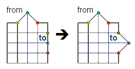
| element normals / XYZ components / by vector / by shape | Choose the direction that the shape is
applied in. For element normals, by vector, and by shape, Engineering Solutions generates one shape for every selected handle in the
direction normal to the surrounding shell elements at the given magnitude. For XYZ
components, Engineering Solutions generates up to three shapes for every
handle selected, based on the directions which you have checked. Figure 4 shows the
preview vectors for eight handles using element normals.
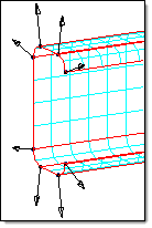 Figure 4. By Normal Figure 5 shows the preview vectors for the same eight handles using by
vector. This option requires you to specify a vector by using the standard plane
and vector selector.
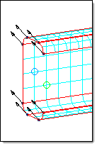 Figure 5. By Vector Figure 6 shows the preview vectors for the same eight handles using XYZ
components. One shape is created for each vector plotted by moving the
corresponding handle the direction and magnitude shown for the vectors.
Note: The XYZ components option creates a shape in each of the selected
directions at the given magnitudes. Therefore, if you select two handles and
all three XYZ components, six shapes are generated, one in each of the X, Y,
and Z directions for both handles.
 Figure 6. By XYZ The by shapes option applies only to spline or polynomial types, and allows you to use a shape to define the perturbation vectors for the handles. The selected shape may have been saved as node perturbations or handle perturbations. In either case the shape will be converted to node perturbations and the perturbations found at the selected handles will be used. |
| handles | Select handles for which shapes will
be created. Note: Only available for standard shapes.
|
| magnitude = | Specify a multiplier for the intensity
of the shape application. For example, 2.0 means double the normal node
displacement while 0.5 means half the displacement. Note: Available for all shape
types when the direction is set to element normals or by vector.
|
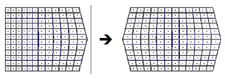
| standard shapes / spline / polynomial | Choose a method for converting each
handle perturbation into a shape.
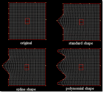 Figure 7. Note: When all the spline or polynomial shapes for a given
domain are applied, the resulting perturbations for the nodes along the domain
sum to the same amount, so if your domain is flat when the shapes are unapplied,
as shown above, it will also be flat when the shapes are all applied by the same
factor. This allows you to create a Fourier-type series with smoothness ensured
across the handles.
|
| syst | Select the coordinate system that the
X, Y, and Z directions correspond to. Note: Available when direction is set to XYZ
components.
|
| use all elems / elems | Choose whether to base the direction
on the normals of all elements, or on only the normals of elements that you select
with an elems collector. Handles usually touch more than one element and that the average normal for those elements is used for the handle. Note: Available
when the direction is set to element normals.
|
Convert Subpanel
Use the Convert subpanel to convert a shape to node perturbations, handle perturbations, or to/from a Force, Temperature, Enforced Displacement, or Pressure load collector. Load collectors can be copied between two meshes by combining this feature with the translate, position, and reflect shapes feature. You can convert a load collector to a shape, then translate, position, or reflect the shape to a new mesh, and then convert it to a load collector.
| Conversion option | Action |
|---|---|
| to node perturbations | Convert the selected shapes to pure node perturbations. Shapes converted to node perturbations will be unaffected by changes to domains and handles but take up more memory. |
| to handle perturbations | Convert the selected shapes to handle perturbations if possible or a combination of handle and node perturbations if it is not possible to capture the shape with pure handle movements. Shapes converted to handle perturbations may be affected by changes to domains and handles but take up less memory. |
| to morph volume shape | Convert a shape which perturbs nodes or handles attached to morph volumes into one which has only handle perturbations for handles on morph volumes. All other perturbations are discarded. If the shape is applied it will morph any nodes registered to the affected morph volumes. Unlike to handle perturbations this option will not preserve node perturbations due to things such as active constraints, and is useful for reverting a shape into pure handle movements and reapplying it with a different set of active constraints. |
| shapes to forces | Create a new load collector for each selected shape with the XYZ perturbations at each node of each shape converted into XYZ values of force vectors at each node for each load collector. The original shape will be preserved and does not need to be converted to node perturbations before conversion to forces. |
| forces to shapes | Create a new shape for each selected load collector with the force vectors at each node of each load collector converted into XYZ perturbations at each node for each shape. The original load collector will be preserved. |
| shapes to temperatures | Create a new load collector for each selected shape with the magnitude of the perturbations at each node of each shape converted into temperature values at each node for each load collector. The node perturbations may lie along any axis and positive and negative temperatures can be preserved by making sure that the nodes are perturbed in only positive or negative directions. The original shape will be preserved and does not need to be converted to node perturbations before conversion to temperatures. |
| temperatures to shapes | Create a new shape for each selected
load collector with the magnitude of the temperatures at each node of each load
collector converted into a perturbation of equal magnitude at each node for each
shape. Note: A temperature of 1000 will be converted in a perturbation
of 5.77.35 in each of the x,y, and z directions. The original load collector
will be preserved.
|
| shapes to pressures | Create a new load collector for each
selected shape with the XYZ perturbations at each node of each shape converted
into XYZ values of pressure vectors at each element for each load collector. Note: Pressures must be averaged from nodes to elements during the
conversion and thus some information maybe lost.
This conversion method
has two options.
|
| pressures to shapes | Create a new shape for each selected
load collector with the pressure vectors at each element of each load collector
converted into XYZ perturbations at each node for each shape. Note: Pressures must be averaged from nodes to elements during the conversion and
thus some information maybe lost. The original load collectors will be
preserved.
|
| shapes to displacements | Create a new load collector for each
selected shape with the XYZ perturbations at each node of each shape converted
into XYZ values of enforced displacements at each node for each load collector.
This conversion method has the option fix directions with zero perturbations which, if checked, will create an enforced displacement for all three translational components for a node even if the displacement for one or two of those components is zero. If not checked, any translations which have zero perturbations will not have an enforced displacement created in that direction. The original shape will be preserved and does not need to be converted to node perturbations before conversion to displacements. |
| displacements to shapes | Create a new shape for each selected load collector with the enforced displacements at each node of each load collector converted into XYZ perturbations at each node for each shape. The original load collector will be preserved. |
Save/Load Subpanel
| Option | Action |
|---|---|
| apply shapes | Apply the shapes automatically upon loading. Clear this checkbox to manually apply shapes in the apply shapes subpanel. |
| auto-envelope / envelope = | The envelope is the range of influence
that a copied shape will have on the new mesh. Use env= to specify an envelope
range if the auto-envelope size does not reach all the nodes you wish to be
morphed. Note: Only available when loading shapes (not grids) and import
direct.
|
| import direct / import via elements |
|
| (shape file path) | Specify the file path for the saved shapes. You can either enter the path, or click browse to navigate to and select the target location and file name. |
| shapes | Select the shapes that you wish to save. |
| as shapes / as grids |
|
| shapes / grids | Specify whether the file to be loaded is a shape file or a gird file. Shape files are generated in Engineering Solutions, while Grid files can originate from OptiStruct, Radioss or Nastran. |
Command Buttons
| Button | Action |
|---|---|
| create | Create a new shape. |
| undo | Undo the most recent node movements associated with a shape. |
| redo | Redo the application of a shape. |
| undo all | Undo all shape-related node movements. |
| reject | Reject the creation of an entity (such as a shape or constraint). This differs from undo because undo only undoes the movement of nodes; rejecting an entity can also undo node movements, but its primary function is to delete an entity that was just created. |
| preview | Once you select the handles and options on the autoshape subpanel, preview allows you to see what shapes will be created before you actually create them. One vector is drawn for each handle perturbation that will be used to create a shape. Click preview again to hide the vectors. |
| return | Exit the Shapes panel. |
| apply | Apply the selected shapes when on the apply shapes subpanel. |
| animate | Automatically generates and loads a "results" file based on the selected shapes, which you can then view with any HyperMesh post processing feature. |
| convert | Convert the selected shapes into the specified type of load collector. |
| save | Save the shape as a shape or grid file. |