Springs Panel
Use the Springs panel to create spring elements.
Location: 1D page
A spring element is an element created in a space between two nodes of a model where a spring connection is desired. In Radioss, three noded or four noded springs can be created.
Spring elements store a property and a degree of freedom (DOF).
Spring elements are element config 21 and are displayed as a line between two nodes with the letter K written at the centroid of the element.
Springs can translate to CELAS2 in Nastran or *SPRING in Abaqus.
Create Subpanel
| Option | Action |
|---|---|
| node 1 |
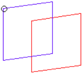
Select the first end of the spring element.
 Figure 1. |
| node 2 |
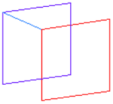
Select end b of the spring element.
Note: Once you select
both end a and end b, Engineering Solutions creates the spring
element.
 Figure 2. |
| no vector / orient vector |
|
| dof1 - dof6 | Select the degree of freedom (DOF) that applies to the element. |
| property | Select a property to which the entity should point. |
Update Subpanel
| Option | Action |
|---|---|
| node 1 |
Select the first end of the spring element.
 Figure 3. |
| node 2 |
Select end b of the spring element.
Note: Once you select
both end a and end b, Engineering Solutions creates the spring
element.
 Figure 4. |
| no vector / orient vector |
|
| dof1 - dof6 | Select the degree of freedom (DOF) that applies to the element. |
| property | Select a property to which the entity should point. |
Spring2, Spring3, Spring4 Subpanel
| Option | Action |
|---|---|
| node | Select the nodes to
create spring elements between. In the Spring3 subpanel, use the third node selector to select the direction node. |
| orientation | Choose a method for
orienting springs in 3D space.
|
Command Buttons
| Option | Action |
|---|---|
| reject | Revert the most recent change. |
| review | After each spring is
selected, Engineering Solutions indicates which degree of
freedom (dof1 through dof6) is active for the element, and also
displays the appropriate values after property = . This function assumes the spring element is active and on the screen. To make a spring element with the same degree of freedom as an existing one, review the existing element. This places the appropriate degree of freedom and property into the panel. |
| update | Implement the changes made in the panel. |
| return | Exit the panel. |