Composites Panel
Use the Composites panel to assign and review the element material orientation of a mesh of shell and continuum shell elements, or to review the fiber direction (ply angle) of individual composite layers.
Element Normals Subpanel
Use the Element Normals subpanel to review, adjust, or reverse element normals.
| Option | Action |
|---|---|
| entity selector |
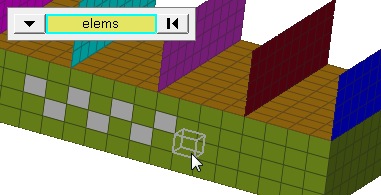
Select elements to display, adjust, or reverse the
normals.
|
| orientation |
Select how bars are oriented in 3D space.
|
| use feature angle | Enter a feature angle (mode=4, and a feature_angle is used). For each connected section, the normals are adjusted for all elements in that section to be consistent with the 'dominant normal direction' already existing within that section, with the sections defined based on the specified feature angle. Clear this checkbox to set the mode=0, and not use a feature_angle. |
| vector display normals / color display normals |
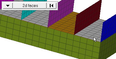
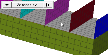
Select a method to review normals of
elements.
|
| display adjusted only | Display the normals which have been changed when you click adjust. |
| display | Display the normals of selected elements or surfaces as vectors or in color mode. |
| adjust | Adjust normals based on the selected orientation method. |
| reverse | Flip all normals of selected elements or surfaces. |
| face angle / individual selection |
|
Material Orientation Subpanel
Use the Material Orientation subpanel to assign systems to elements or properties.
If you change a system after assignment it will only affect the material orientation if by system id has been used. In all other cases the angle calculated at the time of assignment will not be updated. To update the angle in those cases, reassign the system to the elements.
In Abaqus, by system axis is the only option available. Systems will be assigned to the properties selected. In case the system has no ORIENTATION attribute, it will be set and a generic name will be given. The appropriate axis of rotation will be set automatically in the card image.
After assignment the material orientation will be shown with drawn vectors. The size can be adjusted in the panel based on model units. The join lines option can be set in case you want to see connected lines instead of the vector review. The color of the vectors or lines can be changed in this panel using the color selector.
| Option | Action |
|---|---|
| entity selector | Select elements or properties for material orientation assignment. Note:
|
| rebar layer | Supports system assignment to the *REBAR LAYER card for
modeling reinforcement. If the checkbox is selected, the REBAR LAYER attribute and a system reference are assigned to SHELL SECTION (homogeneous and composite), MEMBRANE SECTION and SURFACE SECTION. Upon assignment the REBAR LAYER
attribute will be set in these properties. Orientations for
these properties can as well be reviewed in this panel if
the flag is set.
Note: Only available in the Abaqus solver
interface.
|
| material orientation method | With the by system id method a system is assigned to the
elements, but in all other methods an angle is relative to nodes
1 and 2. An exception is the Abaqus
solver interface, where a system is assigned by system axis to
the property made in the panels selection.
|
| size= | Enter a value in model units that specifies the length of the vectors for reviewing the material orientation. |
| join lines | Connect lines instead of vectors. |
| color | Select a color to assign vectors or lines for review. |
| assign | Assign a material system to the selected elements or properties. Either a system reference will be made, or the selected system axis or the vector will be projected onto the element surface. After performing this operation, the material orientation will be highlighted by either vectors or lines. |
| reset | Reset the material orientation review. |
| review | Select elements or properties for which you want to see the material orientation. |
Ply Directions Subpanel
| Option | Action |
|---|---|
| entity selector | Select elements or properties to review ply directions. |
| rebar layer | Review the rebar orientation angle for each individual layer,
in cases where the GEOMETRY=CONSTANT type is used. Note: Only
available in the Abaqus solver
interface.
|
| review methods |
|
| size | Specify a value in model units that specifies the length of
the vectors for reviewing ply directions. This only affects visualization, not any calculations. |
| join lines | Connect lines instead of vectors. |
| color | Select a color to assign vectors or lines for review. |
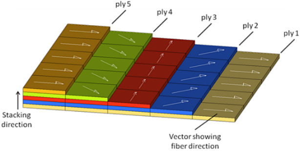
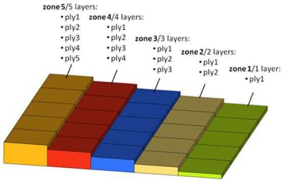
| review | Review ply directions. Select elements or properties and ply= when dealing with a zone based or a global zone based model. For a ply based model you only need to select the ply of interest by clicking ply=. |
| reset | Clear the ply direction review visualization vectors or lines. |
