Midmesh Panel
Use the Midmesh Panel to automatically generate a mesh at the midplane location, directly from the input geometry (components, elements, solids or surfaces), without first creating a midsurface.
Create Subpanel
Use the Create subpanel to control the resulting midmesh output.
- entity selector
- Select the source used to create the midmesh.
- Destination component
- Select which component newly created midmeshes are placed in.
- Ignore flat edges
- Do not imprint flat edges from the input geometry onto the
midmesh.
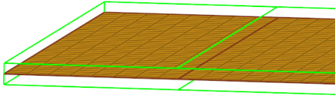
Figure 1. Option Off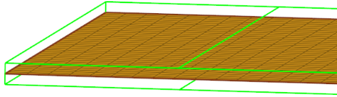
Figure 2. Option On - Flatten connections
- Aligns/flattens the midmesh at ribs/connections.
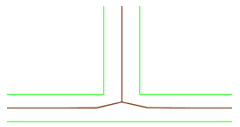
Figure 3. Option Off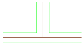
Figure 4. Option On - Step offset mode
- This option allows finer control of how stepped geometry (one side continuous surface, and opposite side steps) is captured. This option is valid only when flatten connections is enabled. Values can be:
- Middle of thinnest plate – All steps that share a
common base are moved to the middle of the thinnest step.
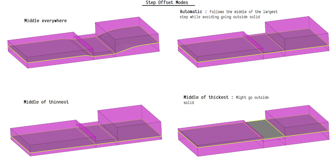
Figure 5. - Edit criteria
- Set the minimum size and target element size settings in the criteria file to control the resulting midmesh via the Criteria File Editor.
- Extraction size
- The midmesh extraction size. By default, this is taken as the target element size from the criteria file. This can be set smaller than the target size, though that is not recommended unless there are problems extracting at the target size.
- Minimum size
- Minimum element size allowed in the finalized mesh. This in combination
with the ‘suppress proximity edges factor’ and 'combine non-manifold
edges factor’ can ensure that the output mesh is ready for rebuild with
the same criteria.
Can only be modified in the Criteria File Editor.
- Suppress proximity edges factor
- The minimum size factor for removing edges within proximity. Edges
closer than this factor times minimum size will be
suppressed.
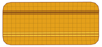
Figure 6. Option Off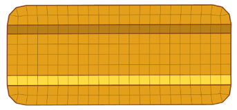
Figure 7. Option On - Combine non-manifold edges factor
- The minimum size factor for joining non-manifold edges. Non-manifold
edges closer than this factor times minimum size will be
combined.
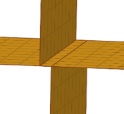
Figure 8. Option Off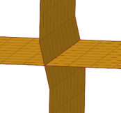
Figure 9. Option On - Defeature ribs width factor
- The minimum size factor for removing small ribs. Ribs closer than this factor times minimum size will be suppressed. Default is 0.9.
- Defeature openings with width <
- The maximum width for removal of small holes and openings.
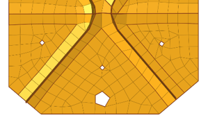
Figure 10. Option Off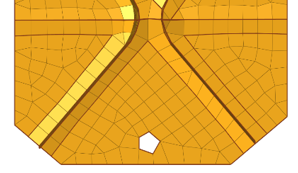
Figure 11. Option On - rebuild mesh...
- Opens the Rebuild Mesh Panel.
- thickness map...
- Opens the Map Midmesh Thickness dialog.
- comparison...
- Opens the Comparison Tool dialog.
Edit Edge Subpanel
Use the Edit Edge subpanel to repair 1D topology edges.
- create mid-edge
- Create a new mid-edge, optionally using the input geometry as a
guide:
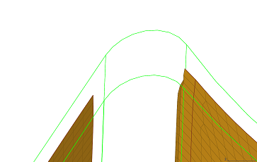 Figure 12. Before
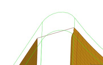 Figure 13. Without Guides
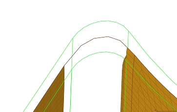 Figure 14. With Guides
 - split by two nodes
- Create a new edge between two nodes.
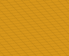
Figure 15. Before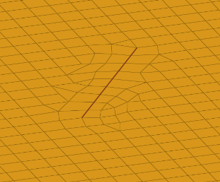
Figure 16. After - split by node-edge
- Create a new edge between a node and an edge, using a shortest,
tangential or mixed path.
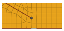
Figure 17. Before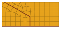
Figure 18. Shortest Path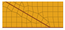
Figure 19. Tangential Path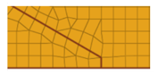 Figure 20. Mixed Path
 - delete edge
- Delete an edge.
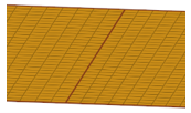
Figure 21. Before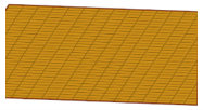
Figure 22. After - t-edge align
- Align/flatten a t-connection edge to a surface.
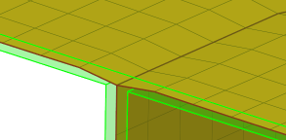
Figure 23. Before
Figure 24. After - by geom edge
- Align mesh edges to input geometry lines and smooth the
mesh:
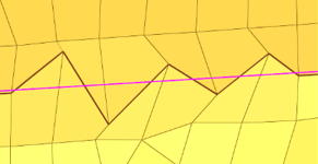
Figure 25. Before Align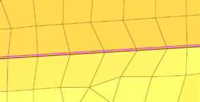
Figure 26. After Align - Imprint geometry edges onto the midmesh:
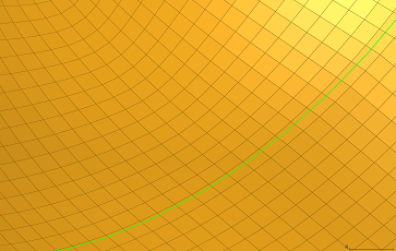 Figure 27. Imprint Before
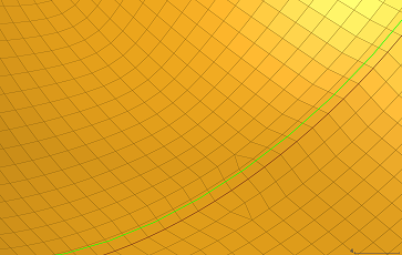 Figure 28. Imprint After
 - replace node
- Opens the Replace Panel.
- edit element
- Opens the Edit Element Panel.
- edges
- Opens the Edges Panel.
- delete
- Opens the Delete Panel.
- align nodes
- Opens the Node Edit panel, align node subpanel.
- project
- Opens the Project Panel.
- rebuild mesh...
- Opens the Rebuild Mesh Panel.
- thickness map...
- Opens the Map Midmesh Thickness dialog.
- comparison...
- Opens the Comparison Tool dialog.
Edit Face Subpanel
Use the Edit Face subpanel to correct issues with midmesh faces.
- fill face
- Create a mesh within a closed 1D topology loop, attempting to keep
tangency. Optionally, the 1D loop can be deleted, keeping only free and
non-manifold edges.
Figure 29. Before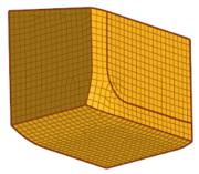
Figure 30. After - repair face
- Attempt to fix topological problems (holes/gaps/cracks, intersections,
slivers, overlaps) in the mesh and remesh the face.
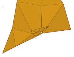
Figure 31. Before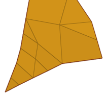
Figure 32. After - detect intersections
- Detect intersecting element clusters and holes/gaps/cracks, and create
element sets for further handling.
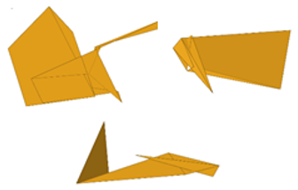
Figure 33. Before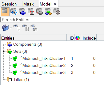 Figure 34. After
 - align face
- Align a selection of elements to an input geometry surface:
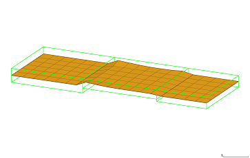 Figure 35. Before
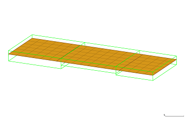 Figure 36. After
 - An optional offset can be specified to align the mesh at a given
distance away from the surface:
 Figure 37. Offset
 - Optional locking of boundary nodes of the selection will treat them as
anchors:
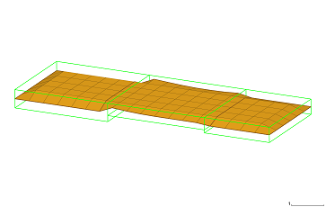 Figure 38. Lock
 - replace node
- Opens the Replace Panel.
- edit element
- Opens the Edit Element Panel.
- delete
- Opens the Delete Panel.
- project
- Opens the Project Panel.
- rebuild mesh...
- Opens the Rebuild Mesh Panel.
- thickness map...
- Opens the Map Midmesh Thickness dialog.
- comparison...
- Opens the Comparison Tool dialog.