Morph Constraints Panel
Use the Morph Constraints panel to create constraints that restrict the movements of nodes or force compliance with dimensional requirements during morphing. Constraints are entities and are saved with the model.
Location: Tools page > HyperMorph module
Panel Usage
Changes made on one subpanel do not affect the other, and are persistent so that you can switch freely between subpanels without losing any settings already made.
You can change the nodes that are associated with a constraint being reviewed by adding or removing them and clicking update. Clicking reject rejects the last constraint created.
You can also release nodes from all of their constraints by accessing the release nodes subpanel, selecting the nodes to be released, and clicking release.
Create/Update Subpanel
Use the Create/Update subpanel to create a new constraint, or to select and modify an existing one.
When a constraint to a line, plane, surface, elements, or an equation is applied, the nodes will be moved to that feature and the node movement will be stored as a morph that can be undone and redone. However, undoing a morph that occurred as part of constraining nodes will not remove the constraint. To remove a constraint after it has been applied, you will need to do one of the following: click reject, use the release feature on the release nodes subpanel, or delete the constraint (via the delete panel).
Nodes may be part of multiple constraints. In these cases, HyperMorph will perform a series of iterations to try to satisfy all of the constraints. For instance, a node constrained to two intersecting surfaces will be moved to a point along the interface between those surfaces. If all of the constraints cannot be met for a given node, HyperMorph will return a warning.
When morphing, constraints are applied after the nodes or handles are morphed. In some cases this may change the amount of morphing applied to the handles or nodes. For instance, when rotating handles which are constrained to move along a line, the handles will first be rotated by the given amount and then moved to line, possibly altering the angle applied to the handles. This is true for all morphing operations except when the distance or angle is changed in the Morph panel, alter dimensions subpanel, which will iterate until both the desired distance or angle is met and the constraints have been satisfied.
For tangency constraints, you are allowed to create tangency "chains" by joining as many 2D or edge domains as desired and even make loops, although main-secondary loops and other insolvable configurations are not allowed. Also, while the 2D domain tangency option is fairly robust, its performance may not be satisfactory when long, curving chains of domains are made tangent to each other. In those cases, the interpolate surf feature in the Map to Geom panel can be used to smooth the mesh.
When a model constraint (length, angle, radius, arc angle, area, volume, or mass) is applied, the shapes associated with the constraint will be applied to the model in order to enforce the constraint. For example, if you have a model that must weigh no more than a certain amount you can create a mass constraint that uses a shape which varies the total width of the model. From then on, after every morph, HyperMorph checks the current weight of the model and, if the model is too heavy, it applies the shape, reducing the width of the model, so that the weight does not exceed the value set in the mass constraint.
| Option | Action |
|---|---|
| along vector: | Define the vector
along which the nodes may travel. Note: Only available for along
vector constraints.
|
| angle | Specify an angle value
to constrain nodes to. This option works in conjunction with the equal to /upper bound / lower bound switch and calculate button. Clicking twice on the label/button opens the calculator. Note: Only available for angle
constraints.
|
| at origin / at node / at system | Choose the starting
point of the path defined by the equation.
Note: Only available for equation
constraints.
|
| arc angle | Specify an angle value
to constrain nodes to. This option works in conjunction with the equal to /upper bound / lower bound switch, calculate button, and find center / center axis / center line / center node switch. Clicking twice on the arc angle label/button opens the calculator. Note: Only available
for arc angle constraints.
|
| area | Specify a total area
to constrain nodes to. This option works in conjunction with the equal to /upper bound / lower bound switch, calculate button, and elems selector. Clicking twice on the area label/button opens the calculator. Note: Only available
for area constraints.
|
| (constraint type switch) | Select the constraint type. |
| color | Select a color for the constraint entity. |
| calculate | Calculate the current
value of the constraint. For example, after selecting nodes for
the node list, click this button to automatically place the
total length of the node list into the length field above
it. Note: Only available for the length, angle, radius, arc
angle, area, volume, or mass constraints.
|
| connected edge domains | Select the edge
domains connected to the constraint. Note: Only available for
smooth constraints.
|
| continuous / main-secondary / fixed end / attached |
Note: Only available for tangency constraints.
|
| create generic | Generate a shape
which, when applied, changes the target constraint value. For
example, once you have specified a node list, you can click this
button to quickly create a basic morph shape that changes the
length of the node list. Note: Only available for length, angle,
radius, arc angle, area, volume, or mass
constraints.
|
| domain | Select the domains
between which the tangency constraint exists. Note: Two of these
selectors is only available for tangency
constraints.
|
| elems | Select the mesh
elements to which the nodes are constrained. For area,
volume, or mass constraints, the area/volume/mass is
calculated from the selected elements (before morphing) and
that total area/volume/mass is maintained after morphing,
though the shape of the element cluster can change.
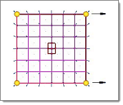 Figure 1. Area Constraint on Elements 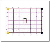 Figure 2. Shape Changes, but Total Area (L x W) is Preserved Note: Only available for elements, area, volume, or
mass constraints.
|
| equal to / upper bound / lower bound | Choose how the value
in the length field is used.
Note: Only available for length, angle, radius, arc angle,
area, volume, and mass constraints.
|
| exclude beyond | Exclude any selected
nodes which are either beyond a certain distance or beyond a
given number of rows of elements away from the selected
elements. In the dialog that opens there are two collectors which match the contents of the nodes and elements in the panel. You can modify the selected nodes and elements by double-clicking these collectors. The dialog also contains an entry field which you can use to enter the number of model units or number of element rows. After the entry field there is a selector which you can use switch between model units and element rows. If model units is selected, any nodes beyond the given number of model units will be excluded from the selected nodes. If element rows is selected, any nodes beyond the given number of element rows away from the selected elements will be excluded from the selected nodes. For element rows, the rows of elements must be attached to the selected elements and all nodes not a part of the rows of elements will be excluded. When exclude is clicked, any nodes beyond the given criteria are removed from the selected nodes. If no nodes have been selected, all the nodes in the model which are not attached to the selected nodes are placed on the mark and those beyond the given criteria are then excluded from the mark. Figure 3
shows how the exclude beyond functionality is used. In the
image on the left, all of the nodes for the crimson mesh and
the elements shown in gray are selected for an on elements
type morph constraint. Using the exclude beyond dialog,
model units is selected as the distance option and a
distance of 1000.0 is used to exclude all of the nodes which
are more than a thousand model units away from the selected
elements. In the image on the right, the exclude has been
clicked and the nodes left on the mark are those at or
within one thousand model units of the selected
elements.
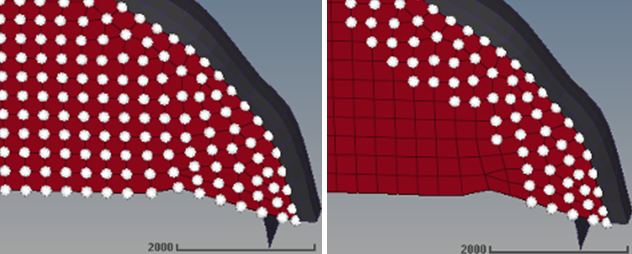 Figure 3. Note: Only available for the elements type morph
constraint.
|
| find center / center axis / center line / center node | Works in conjunction
with the edge domain selector to help determine the correct
value for the radius or arc angle numeric boxes.
|
| F(xyz) | Select an equation.
Text fields will be automatically populated upon selection. Edit
these equations if necessary. Replace constants a, b, c, r, and R with numbers. For more complex shapes defined by more than one equation (such as a torus) the corresponding equations fill into each of the two text fields. You can also specify your own function. The function may contain x, y, and z variables with the rest being numbers or expressions. The surface defined when the function is set to zero will be used as the boundary for the constraint. You can add more equations by means of the prev and next buttons. Note: Only available for equation
constraints.
|
| fix dofs: | Constrain the degrees
of freedom of the nodes for a given coordinate system for an
along dofs constraint.
|
| fixed at: node | Select the node that
is the fixed point for the end which is to be
constrained. Note: Only available for tangency constraints of
type fixed end.
|
| fully fixed / translate only / force normal / allow sliding | Choose how the inner
layers of a fixed layers style constraint on elements will move
when the outer layer is morphed.
|
| global system / syst | Choose a global system/local system for an along dofs constraint. The degrees of freedom of the system selected will be used for all the nodes of the constraint. |
| length | Specify a total length
value to constrain nodes to. This option works in conjunction
with the equal to /upper bound / lower bound switch, calculate
button, and node list selector. Clicking twice on the length label/button opens the calculator. Note: Only available
for length constraints.
|
| line | Select the line along
which nodes are allowed to move. Note: Only available for along
line constraints.
|
| mass | Specify a total mass
value to constrain nodes to. This works in conjunction with the
equal to /upper bound / lower bound switch, calculate button,
and elems selector. This value is calculated based on the area/volume of the selected elems, and density data supplied by a property card. The total mass remains fixed after morphing, even if the shape of the element cluster changes. Clicking twice on the mass label/button opens the calculator. Note: Only available for mass
constraints.
|
| measured along | Choose what vector or
path the length is measured along.
|
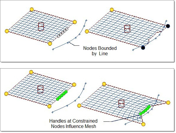
| moves along / bounded / set distance / fixed layers |
Note: Only available for along vector, along line, on plane, on
surface, on elements, and on equation constraints. Each type
of constraint involves different additional inputs, which
display when the combination of constrain type and moves
along / bounded / set distance / fixed layers is selected
(each of these additional fields are described later in this
table).
|
| measured normal to: | Choose what the angle
is measured relative to.
Note: Only available for angle constraints.
|
| name = | Specify a name for the
new constraint to create. To update an existing constraint, either enter its name, or click the button twice and select the desired constraint. |
| node a / vertex / node b | Define the angle for angle constraints. Once you define these nodes, click calculate to automatically populate the angle numeric box. |
| nodes | Select the nodes to be constrained individually in the modeling window, or use the extended entity selection menu to select groups of nodes by certain criteria. |
| node list | Select nodes to define
the boundaries of the length constraint, and to enable the use
of the create generic and calculate buttons, as well as the use
of the node list option for measured along. Note: Only available
for length constraints.
|
| on plane: | Define the plane to
which the nodes are constrained. Note: Only available for plane
constraints.
|
| project along: | Nodes that you select
which don't already lie on the constraint entity will be
projected to it in this direction. In addition, during
morphing the nodes constrained to such entities may move off
of them, but will then be projected in this direction back
onto the constraint entity when the morph action finishes.
(If you want the nodes to remain exactly fixed, without
sliding along the entity, use a fixed constraint for them
instead.)
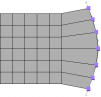 Figure 6. Project to Line Normal 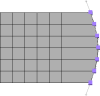 Figure 7. Project Using a Vector Note: Only available for along line, on plane, on
surface, on elements, or on equation
constraints.
|
| radius | Specify a radius value
to constrain nodes to. This option works in conjunction with the equal to /upper bound / lower bound switch and calculate button. The radius is measured using an edge domain and one of the following methods for finding the center of curvature: an axis, a line, a node, or inferred from the plane of the edge domain. Clicking twice on the radius label/button opens the calculator. Note: Only
available for radius constraints.
|
| (rotation switch) | Choose between no
rotation, tilt only, spin only, and full rotation. The spin
(in plane) and tilt (out of plane) options only apply for
cluster constraints whose nodes all lie in a plane. If the
nodes do not lie in a plane, any rotation option is
considered full rotation.
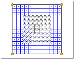 Figure 8. Cluster Constraint  Figure 9. Cluster Constraint with no Rotation 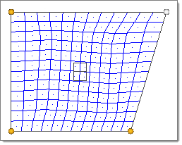 Figure 10. Cluster Constraint with Spin or Full Rotation Enabled Note: Only available when the constraint type is
set to constraint.
|
| shapes | Select pre-existing
shapes, or create generic shapes from the node list. Note: Only
available for length, angle, radius, arc angle, area,
volume, and mass constraints.
|
| smooth nodes / smooth dep. handles | Choose how to apply
the spline-based motion of smooth edge constraints.
Note: Only available for smooth constraints.
|
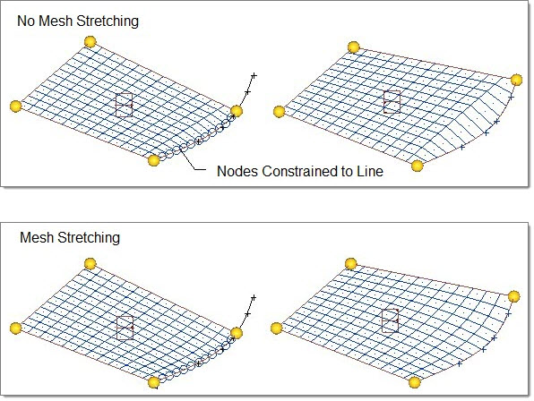
| stretch mesh around nodes |
Stretched the mesh near the constrained nodes proportionally
to their distance from the nodes, in order to create a smoother resulting mesh.
Clear this checkbox to not stretch the mesh.
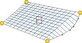 Figure 11. No Mesh Stretching 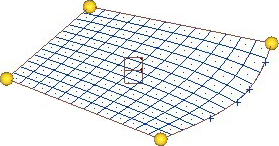 Figure 12. Mesh Stretching Enabled |
| surf | Select the surface to
which the nodes are constrained. Note: Only available for surf
constraints.
|
| volume | Specify a total volume
value to constrain nodes to. This option works in conjunction with the equal to / upper bound / lower bound switch, calculate button, and elems selector. Clicking twice on the volume label/button opens the calculator. Note: Only available for volume
constraints.
|
Release Nodes Subpanel
Use the Release Nodes subpanel to free specific nodes from any constraints they might be part of. You can pick nodes individually, or use the extended entity selection menu to pick groups of nodes by certain criteria.
The Release Nodes subpanel contains only a single nodes entity selector, and the release command button.
Command Buttons
| Button | Action |
|---|---|
| create | Create a new constraint entity using the specified characteristics. |
| update | Update the specified nodes to use the currently specified constraint. |
| apply | Apply the current constraint to the selected nodes. This can be used to change/update the qualities of the constraint without changing the nodes that it applies to. |
| undo | Move constrained nodes
back to their original locations (for example, when nodes are
constrained to a line), but do not remove their association with
the constraint. Click Apply to reapply the constraint (which will apply all active constraints) or perform another morphing operation. |
| redo | Redo the most recently undone action. |
| reject | Reject the creation of an entity (such as a shape or constraint). This differs from undo because undo only undoes the movement of nodes; rejecting an entity can also undo node movements, but its primary function is to delete an entity that was just created. |
| release | Release the selected nodes from any and all constraints. |
| prev | Go to the previous
list of equations. Note: Only available for equation
constraints.
|
| next | Go the next list of
equations. Note: Only available for equation
constraints.
|
| return | Exit the panel. |