Seam Panel
Use the Seam panel to create connectors that represent line connectors such as seam welds. These connectors can later be realized as standard or custom weld representations.
Location: Connectors module
When the Seam panel is active, only seam-type connectors display in the modeling window; graphics for other connector types are suppressed until you exit the panel.
Subpanel Organization
- Seam Subpanel
- Create and realize seam connectors.
- Create Subpanel
- Create, but do not realize seam connectors.
- Realize Subpanel
- Realize existing seam connectors (no creation or editing possible).
- Edit Subpanel
- Edit existing seam connectors.
- Partition Subpanel
- Partition (separate into sections of connections that passed or failed valid projections) an existing seam connector.
- The first column contains everything related to connector creation and link detection.
- The second column contains everything related to realization type, post script and property assignment.
- The third column contains everything related to the final connection to the link entities.
Connector Creation and Link Detection Options
| Option | Action |
|---|---|
| location | Specify the location of the connector to be created.
|
| spacing/density |
|
| retain nodes | Retain the position of the nodes when you create and realize a
connector. Note: Only available if location is set to nodelist.
|
| connectors | Select the connector(s) to be realized. |
| line combine |
Create one seam connector for each sequence of lines and each single line. With this option enabled, a sequence of lines will be internally treated as on line. This option is preferred for continuous seams together with realization types where the body element is positioned between the weld points of all quad and hexa seam realizations. With this option, neither the vertices nor the start point
and end point of the initial lines are considered, and there likely will not be any
weld points at the exact positions.
Note: Default setting when location is set to
linelist.
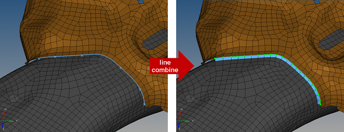 Figure 1. 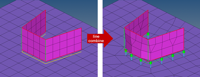 Figure 2. |
| group CE |
Create one seam connector from each selected line, and group those
seams which form a sequence of seam connectors together. Each group of connectors is
then treated as a single connector entity. Each connector in the group has the same
display mode, same realization state, and so on. Furthermore the start points and
end points of two sequenced connectors in that group are treated as being one point.
This fact allows this option also to be used together with realization types where
the body element is positioned between the weld points, such as for all quad and
hexa seam realizations. For hexa seams and for use of quad transition, the vertex
angle has to be quite small to prevent bad hexa elements or imprint
conflicts.
Note: The selected lines need to be longer than half the spacing
length, otherwise the lines are ignored.
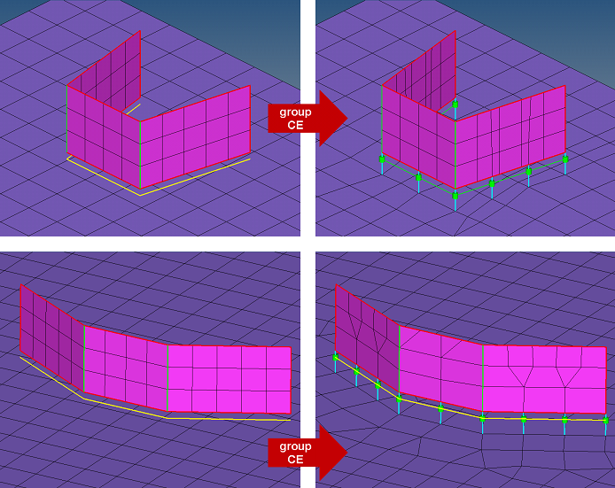 Figure 3. |
| do not group CE |
Create one seam connector from each selected line. Even those
seams which form a sequence of seam connectors are not grouped together. The start-
and end- points of two sequenced connectors in that group are treated as being
different points. This fact makes the use of quad transition impossible for
sequenced seam connectors, because the imprint patterns will always conflict each
other.
Note: The selected lines need to be longer than half the spacing length,
otherwise the lines are ignored.
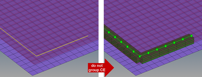 Figure 4. |
| connect what |
Select the entities to
become link candidates. Link candidates are certain entities of a chosen link
type, which are supposed to be connected during the realization. Entities
outside the tolerance are not taken into account.
Note: Connectors can be created with different
types of entities; for example, a connector can be defined by selecting a
component on one side and an assembly on the other side. This can be done by
creating a connector to specify one of the entity types and selecting that
entity. Add the second entity by updating the connector via the add links
functionality in the Connector browser or the Add Links panel.
|
| num layers |
Define how many thicknesses (layers) have to be connected at the connector position. This number is predefined as 2. There is not a field in the this panel where you can set the number of layers; however, you can find the number of layers in the Connector browser. When link detection is performed the valid connector links are established with respect to the given tolerance and the selected link candidates. By default the links are reduced to the minimum needed. The number of links is typically higher than the number of layers, because a valid pair of projections need to be found per test point. |
| tolerance |
Define a distance from the connector location (per each test point). Only entities within this tolerance can be taken into account for the link detection and the final realization. Thus, the tolerance is used twice: first for the link determination and again for the realization. In the second step the tolerance is used to verify whether adequate link candidates are available to be connected. During pure connector creation on the Create subpanel, the tolerance is used for the link determination, but not necessarily stored on the connector unless the checkbox in front of the tolerance field is marked. In this way different tolerances can be used. The tolerance used during the realization process is always written to the connector. |
| connect when |
Select when to perform link detection.
|
| reconnect rule |
While realizing the connector, Engineering Solutions
looks for link entities based on the re-connect rule.
Tip: This option is
useful in situations where the parts to be connected have been
changed/replaced.
|
| reverse direction | During the first realization of a seam its direction is
determined. Even though this direction is only important for
realization types which use angle information like seam-quad
(angled), every seam gets this direction. Therefore the reverse
direction checkbox only appears for angled seams. The direction
can only be reversed during the next realization if the checkbox
is enabled.
Note: Normally this option is only needed for
T-welds, because in that case there isn’t any indication for
the probable direction.
For this reason, if an angled
T-weld should be realized together with quad transition, it
might be useful to skip the imprint in the first step and review
the assumed direction. Rerealize all wrong directed seams with
the checkbox enabled. If all directions are correct, uncheck the
option and rerealize with active imprint. This procedure
prevents the mesh from being interfered more often than
necessary. |
Post Script and Property Assignment Options
| Option | Action |
|---|---|
| type |
Select the realization type which should be used. The
realization type is a description of the FE representation.
Note: The available
realization types are dependant on the configuration file loaded under fe file
on the general connector Options panel.
|
| post script treatment |
Choose whether or not a post script has to be used for
the specific realization type. These scripts are used to automatically create
materials, properties, and/or contacts necessary for realizing the connectors.
|
| elems to current comp / connector comp |
Select which component the FE representations
are stored in once they have been realized.
Note: Only available in the realize subpanel when post script treatment is set
to no/skip post script.
|
| property treatment |
Select a property treatment.
Note: Only available when post script treatment is set to no/skip post
script.
|
| direct property assignment |
Directly assign the property, otherwise assign the
property to the destination components.
Note: Only available when property treatment
is set to property =, and the solver interface is Nastran, OptiStruct, Radioss or Abaqus.
|
Quad Realization Options
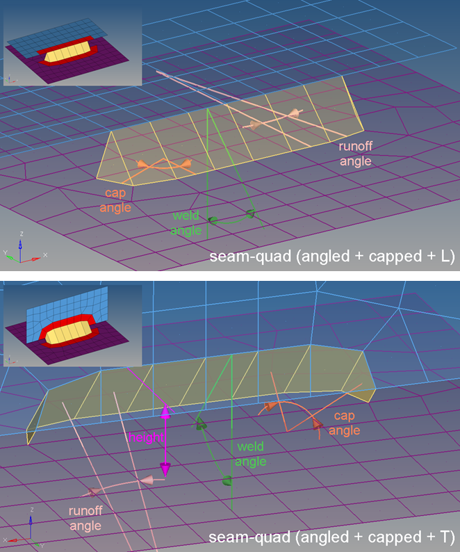
Figure 5.
| Option | Action |
|---|---|
| weld angle | Define the distance between the normal projection and the
quad direction. Principally it is allowed to define weld angles between 0.0 and 90.0. If the value is set to 0.0 an internal thickness-based calculation is used. If the value is set to 0.0 and no thickness is defined the connector will fail. If the angle is created in the wrong direction, the seam can be reverted by enabling the reverse direction checkbox and performing a rerealization. |
| cap angle | Depending on the seam-quad type, the cap angle is measured
differently.
Cap angles are created by default. Clear this checkbox to remove cap angles and runoff angles. Cap angles
between 0.0 and 45.0 are permitted, but be aware that larger
values can lead to bad elements. The recommended value is
10.0 or smaller. Cap angles between 45.0 and 90.0 are
permitted, but be aware that smaller values lead to bad
elements. The recommended value is 75.0 and
higher.
Note: Only available for seam-quad (angled +
capped + L) and seam-quad (angled + capped +
T).
|
| runoff angle | Depending on the seam-quad type, the runoff angle is measured
differently.
|
| height | Define the distance between the projection point and the
start-point of the angled quads. Note: Only available for
T-seams.
The height needs to be chosen in an extent to
bridge the gap between the links. Also, the height strongly
influences the quad length, especially in cases of very large
weld angles. |
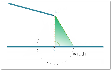
Hexa Realization Options
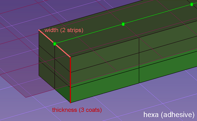
Figure 6.
| Option | Action |
|---|---|
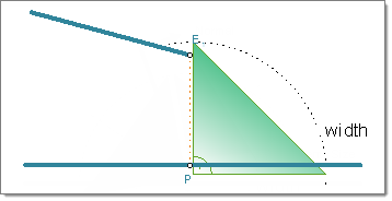
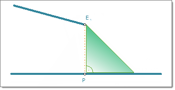
| width | Define the width of the continuous hexa weld in the direction
perpendicular to the seam direction. Note: Only available for
hexa (adhesive) and hexa (RBE2-RBE3).
|
| strips | Define the number of hexa elements required along the width. |
| coats | Defines the number of hexa elements required along the thickness. |
| thickness |
Select a method for defining the thickness of a hexa
weld.
Note:
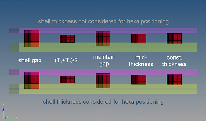 Figure 7. |
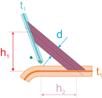
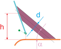
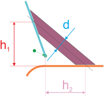
| thickness dependent / angle, D and H / H1, H2 and D | Hexa (tapered T) enables you to create tapered seam hexas for
T-connections. Select a method to define how hexas are
positioned and located, and assign appropriate values to any
corresponding inputs.
|
| discontinuity | By default, the length and pattern of a hexa weld is defined
by test points along the seam connector. To ignore the
predefined test points, and define a specific element length,
weld length, and break length to realize the connector with,
select the discontinuity checkbox. With this option, a hexa
adhesive seam with alternating weld pieces and gaps is created.
When discontinuity is enabled, you must define the
following inputs:
Note: Only available for
hexa (adhesive) realizations.
|
| hexa position to edge | Select a location to create the hexa from the edge.
Note: Only
available for hexa (adhesive) and hexa
(RBE2-RBE3).
|
| edge details |
In many cases, the connector position is not very
precise. To create the requested result, an automatic edge snapping can be enabled.
In the first step the connector snaps to, for example, the closest free edge, and
then from there the projection and FE creation starts. Select how many element rows
away from the free edge to snap the connector to for L and T connections.
|
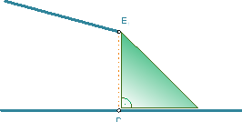
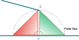
Penta Realization Options
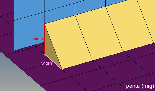
Figure 11.
| Option | Action | ||||||
|---|---|---|---|---|---|---|---|
| width | Specify the length of a penta. Note: Only available for penta
(mig), penta (mig + L), penta (mig + T), and penta (mig +
B).
|
||||||
| fitted/equilateral/equilateral-fitted |
Select the size and shape
of a penta.
Note: Only available for penta (mig) and penta (mig + L).
|
||||||
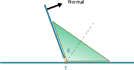
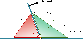
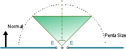
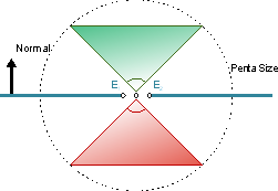
| right-angled |
Create a right-angled penta that is oriented around the
bisector. Clear this checkbox to create an angle adapted penta.
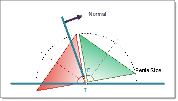 Figure 15. Right-Angled T-weld Penta Created on Both Sides of the Normal 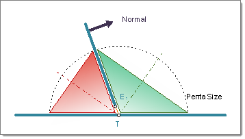 Figure 16. Angle Adapted T-weld Penta Created on Both Sides of the Normal Note: Only available for penta (mig) and penta (mig + T).
|
||||||
| both sides/positive sides/negative sides |
Select which side of the normal to create
the penta on.
Note: Only available for penta (mig), penta (mig + L), penta
(mig + T), and penta (mig + B).
|
||||||
| edge details |
In many cases, the connector position is not very
precise. To create the requested result, an automatic edge snapping can be enabled.
In the first step the connector snaps to, for example, the closest free edge, and
then from there the projection and FE creation starts. Select how many element rows
away from the free edge to snap the connector to for L and T connections.
|
Other Seam Realization Options
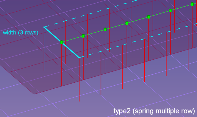
Figure 20.
| Option | Action |
|---|---|
| row | Specify how many rows of spring elements have to be created. The rows are parallel to the seam connector. The rows are distributes equidistant through the width. |
| width | Specify the distance between the outermost element rows. |
Final Connection to Link Entities Options
| Input | Action |
|---|---|
| mesh dependent/ mesh independent |
Determine whether the realizations require
a node connection.
|
| adjust realization / adjust mesh |
Note: Only available when mesh independent is selected.
|
| quad transition / remesh | Select a mesh
adjustment method.
Note: Only available when mesh dependent and adjust mesh
are selected.
|
| imprint / skip imprint |
Note: Only available when mesh independent, adjust mesh, and quad transition are
selected.
|
| use pitch size to imprint / use avg. mesh size to imprint / size to imprint | Select a method to
determine the size of the imprint.
Note: Only available when mesh dependent, adjust mesh, and
quad transition are selected.
|
| find nearest nodes / project and find nodes / ensure projection | Determine how the
realization will adjust to locate nodes in the linked entities
in order to establish links. This decision can be quite
involved. Note: Only available when adjust realization is
selected.
|
Edit Subpanel Options
| Option | Action |
|---|---|
| connector | Select the seam connector that you would like to trim. |
| node | Select the point that you would like to trim the connector at. |
| snap to connector point | Trim the connector at specific points within a specified
tolerance.
By default this option is selected, and the tolerance is set to 1.0. If you clear this checkbox, connector points will be equally distributed when the connector is trimmed. |
| delete smaller connector piece | Delete the smallest connector piece when the connector is trimmed. |
| trim | Trim the connector into a new, unrealized connector. The new connector contain all of the information that was retained from the original connector. |
| Option | Action |
|---|---|
| connectors | Select connectors. |
| spacing/density |
|
| end offset / half spacing |
|
| Option | Action |
|---|---|
| connectors | Select connectors. |
| connect rule |
|
Seam Partitioning Options
| Inputs | Actions |
|---|---|
| connector | Select the
connector(s) that you wish to be partitioned. Clicking partition updates the selected connectors with respect to the newly chosen settings. The connectors will become unrealized. |
| non-normal projection | Clear this checkbox to
consider only points with two valid "normal" projections as
passed points during the partition. Tip: This is the
recommended setting, especially if the seam connector should
be realized as a hexa row afterwards.
|
| tolerance | Use the given
tolerance for the projection test and the newly created
connectors. Clear this checkbox to use the tolerance stored on each connector for both the projection test and the newly created connectors. |
| organize connectors with passed projections | Select where to
organize the newly created "passed" connectors.
|
| number passed connector IDs | Select how the newly
created "passed" connectors are numbered.
|
| organize connectors with failed projections | Select where to
organize the newly created "failed" connectors.
|
| number failed connectors IDs | Select how the newly
created "failed" connectors are numbered.
|
| backup original connectors | Select whether the
original connectors should be backed up or not.
|
Command Buttons
| Button | Action |
|---|---|
| group/ungroup | Apply grouping or ungrouping to a set of connectors. |
| options | Open the connector options panel where various settings can be defined. |
| edit | Apply spacing, density, or offset changes to a connector. |
| create | Create the connector(s) with provided input (if sufficient). |
| partition | Apply the partitioning onto the selected connectors, using the provided input. |
| reject | Undo the last action. |
| return | Exit the seam panel. |