OptiStruct is a proven, modern structural solver with comprehensive, accurate and scalable solutions for linear and nonlinear
analyses across statics and dynamics, vibrations, acoustics, fatigue, heat transfer, and multiphysics disciplines.
Descriptions for individual I/O Option Entries can be accessed by selecting from the links for each entry, listed
below in groups according to their purpose and alphabetically on the I/O Options section page.
Descriptions for individual Subcase Information Entries can be accessed by selecting from the links for each entry,
listed below in groups according to their purpose and alphabetically on the Subcase Information Section page.
Bulk Data Entry Defines acceleration loads to all grids in the model. These loads can either be constant or vary in a particular direction
over sections of the model.
Bulk Data Entry Defines static acceleration loads at a specific SET of GRID points in the model. Additionally, scale factors for varying
direction acceleration loads can be defined using tabular data.
Bulk Data Entry Specifies an aerodynamic control surface as a member of the set of aerodynamic extra points. The forces associated
with this controller will be derived from rigid rotation of the aerodynamic model about the hinge line(s).
Bulk Data Entry Indicates the beginning of data that is used to describe a specific entity (or entities) for inclusion in a model.
The BEGIN entry is used in conjunction with the END entry to define the data required for a specific entity.
Bulk Data Entry Defines an aerodynamic macro element (panel) in terms of two leading edge locations and side chords. This is used
for Vortex Lattice Method (VLM) and Doublet Lattice Method (DLM) in subsonic aeroelastic analysis.
Bulk Data Entry Defines a current density on the face of solid elements (HEXA, PENTA, TETRA, PYRA) or on the side of shell elements
(TRIA3, TRIA6, QUAD4, QUAD8), in Electrical analysis.
Bulk Data Entry Defines a scalar spring element of the structural model without reference to a property entry. The corresponding properties
on this entry are not affected by translational and rotational stiffness limits specified using PARAM,ELASSTIF.
Bulk Data Entry Defines a scalar spring element that is connected only to scalar points without reference to a property entry. The
corresponding properties on this entry are not affected by translational and rotational stiffness limits specified
using PARAM,ELASSTIF.
Bulk Data Entry Defines the CMS (Component Mode Synthesis) method, frequency upper limit, number of modes, and starting SPOINT ID to be used in a CMS solution.
Bulk Data Entry Defines parameters for stabilization control of contact (S2S and N2S) and gap elements (CGAP/CGAPG). This entry is supported with nonlinear static and nonlinear transient analysis types for both small and
large displacement cases.
Bulk Data Entry Define equivalence for degrees of freedom of grid points of two sections of the same model (Format 2) or different
parts in a Parts and Instances Model (Format 1) within a specified tolerance.
Bulk Data Entry Defines Free convection via automatic generation of free convection entries. This entry also supports subcase-dependent
free convection.
Bulk Data Entry Defines a cylindrical coordinate system using three grid points. The first point is the origin, the second lies on the Z-axis, and the third lies in the X-Z plane.
Bulk Data Entry Defines a rectangular coordinate system using three grid points. The first point is the origin, the second lies on the Z-axis, and the third lies in the X-Z plane.
Bulk Data Entry Defines a spherical coordinate system using three grid points. The first point is the origin, the second lies on the Z-axis, and the third lies in the X-Z plane.
Bulk Data Entry Defines a rectangular coordinate system using three grid points. The first point is the origin, the second lies on the X-axis, and the third lies in the X-Y plane.
Bulk Data Entry CTRIAR entry is equivalent to CTRIA3. Unlike other Nastran codes, a 6 degrees-of-freedom per node formulation is used for all shell elements.
Bulk Data Entry Define real, discrete design variable values for discrete variable optimization or to define relative rotor spin rates
in rotor dynamics.
Bulk Data Entry Defines the time delay term in the equations of the dynamic loading function. DELAY is used in conjunction with RLOAD1, RLOAD2, TLOAD1, and TLOAD2 entries.
Bulk Data Entry Defines a link between a DIM# field on a PBARL or PBEAML property and either the thickness on a PSEC definition or the y or z coordinate on a GRIDS definition; it is used in the definition of arbitrary beam cross-sections.
Bulk Data Entry Defines parameters for filling a space with lattice-based unit cells. The presence of this entry also activates the
creation of unit cells to fill the target volume.
Bulk Data Entry Defines a link of one design variable to one or more other design variables defined by a DEQATN card. The equation inputs come from the referenced DESVAR values and the constants defined on the DTABLE card.
Bulk Data Entry Defines a dynamic loading condition for frequency response problems as a linear combination of load sets defined via
RLOAD1 and RLOAD2 entries, or for transient problems as a linear combination of load sets defined via TLOAD1 and TLOAD2 entries, or acoustic source ACSRCE entries.
Bulk Data Entry Defines direct input matrices related to grid points. The matrix is defined by a single header entry and one or more
column entries. A column entry is required for each column with non-zero elements.
Bulk Data Entry Defines the phase lead term in the equation of the dynamic loading function. DPHASE is used in conjunction with RLOAD1 and RLOAD2 entries.
Bulk Data Entry Used in the Bulk Data section to report responses, defined by DRESP1, DRESP2 and DRESP3 cards, to the output file, which are not constrained or used as the objective function, as defined by the optimization
problem.
Bulk Data Entry A response or a set of responses that are the result of a design analysis iteration. These responses can
be used as a design objective or as design constraints.
Bulk Data Entry Relates design variables to an analysis model element property using a relationship defined by a DEQATN card. The equation inputs come from the referenced DESVAR values and constants defined on a DTABLE card.
Bulk Data Entry Relates a design variable to an analysis model loading using a relationship defined by a DEQATN card. The equation inputs come from the referenced DESVAR values and the constants defined on the DTABLE card.
Bulk Data Entry Relates a design variable to properties of MBD entities using a relationship defined by a DEQATN card. The equation inputs come from the referenced DESVAR values and the constants defined on the DTABLE card.
Bulk Data Entry Relates design variables to an analysis model material property using a relationship defined by a DEQATN card. The equation inputs come from the referenced DESVAR values and constants defined on a DTABLE card.
Bulk Data Entry Relates a design variable to an analysis model property using a relationship defined by a DEQATN card. The equation inputs come from the referenced DESVAR values and the constants defined on the DTABLE card.
Bulk Data Entry The END Bulk Data Entry indicates the end of data that is used to describe a specific entity (or entities) for inclusion
in a model. The END entry is used in conjunction with the BEGIN entry to define the data required for a specific entity.
Bulk Data Entry Defines a combined time step selection set as a union of selected time steps defined via ESLTIME entries for Geometric Nonlinear ESLM optimization or a Multibody Dynamics ESLM optimization.
Bulk Data Entry Defines a set of frequencies to be used in the solution of frequency response problems by specification of a starting
frequency, frequency increment, and the number of increments desired.
Bulk Data Entry Defines a set of frequencies to be used in the solution of frequency response problems by specification of a starting
frequency, final frequency, and the number of logarithmic increments desired.
Bulk Data Entry Defines a set of frequencies for the modal method of frequency response analysis by specifying the number of frequencies
between modal frequencies.
Bulk Data Entry Defines a set of frequencies for the modal method of frequency response analysis by specifying the amount of "spread"
around each modal frequency and the number of equally spaced frequencies within the spread.
Bulk Data Entry Defines a set of frequencies for the modal method of frequency response analysis by specification of a frequency range
and fractions of the natural frequencies within that range.
Bulk Data Entry Defines parameters that control connectivity and configuration checks for gap elements (CGAP and CGAPG). Most of these parameters also affect contact elements that are automatically created on CONTACT interfaces - see individual descriptions for details.
Bulk Data Entry Defines the stiffness, flexibility, mass, viscous damping, or structural damping of a general element connected to
an arbitrary number of grids.
Bulk Data Entry Defines equivalence for all degrees of freedom of grid points of two different subsets of without any requirement
that these two subsets are closely located to one another.
Bulk Data Entry Defines the gravity vectors for use in determining gravity loading for the static structural model. It can also be used
to define the EXCITEID field (Amplitude "A") of dynamic loads in RLOAD1, RLOAD2, TLOAD1, TLOAD2 and NLOAD1 Bulk Data Entries for dynamic solution sequences.
Bulk Data Entry Defines the location of a geometric grid point of the structural model, the directions of its displacement, and its permanent
single-point constraints or permanent zero electric potential.
Bulk Data Entry The INSTNCE Bulk Data Entry can be used to define the location of a part in the global structure. Each INSTNCE entry should reference a unique part name.
Bulk Data Entry Defines a static load as a linear combination of load sets defined via FORCE, MOMENT, FORCE1, MOMENT1, PLOAD, PLOAD1, PLOAD2, PLOAD4, RFORCE, DAREA, ACCEL, ACCEL1, ACCEL2, GRAV and LOADADD entries.
Bulk Data Entry The LOCATE Bulk Data Entry can be used to define the location of a part in the global structure. Each LOCATE entry should reference a unique part name. LOCATE Bulk Data Entries are activated in each subcase by the LOCATE Subcase Entry.
Bulk Data Entry Defines the material properties for linear, temperature-independent, and orthotropic materials used by the CTAXI, CTRIAX6, and CQAXI axisymmetric elements, and CTPSTN and CQPSTN plane strain elements.
Bulk Data Entry Defines the material properties for linear, temperature-independent, and orthotropic materials for solid elements
in terms of engineering constants.
Bulk Data Entry Defines material properties and parameters through an interface to AltairMultiscale Designer® allowing you to include a much wider range of different material models.
Bulk Data Entry Defines options for user-defined input of frequency ranges used to define bands in adaptive meshing for acoustic Adaptive
Perfectly Matched Layer (APML) analysis.
Bulk Data Entry Used to define properties of a virtual fluid mass. A virtual fluid mass mimics the mass effect of an incompressible
inviscid fluid in contact with a structure.
Bulk Data Entry To input a table of Mach number (M) and reduced frequency (K) pairs for aerodynamic matrix calculation, in unsteady
aerodynamic analysis.
Bulk Data Entry Defines a multibody as a linear combination of load sets defined via GRAV, MBFRC, MBFRCC, MBFRCE, MBMNT, MBMNTC, MBMNTE, MBSFRC, MBSFRCC, MBSFRCE, MBSMNT, MBSMNTC, and MBSMNTE.
Bulk Data Entry Defines an integrated load monitor point at a point (x,y,z) in a user-defined coordinate system. The integrated loads
about this point over the associated loads will be computed and printed to the .monpnt file.
Bulk Data Entry Defines parameters for energy variables printout for implicit nonlinear static, implicit nonlinear transient analyses,
and explicit dynamic analysis.
Bulk Data Entry Defines properties for CAERO1 panels. This is used for Vortex Lattice Method (VLM) and Doublet Lattice Method (DLM) in subsonic aeroelastic analysis.
Bulk Data Entry Defines up to four sets of grid points or elements as panels for panel participation output for a frequency response
analysis of a coupled fluid-structural model.
Bulk Data Entry Defines the various nominal property values for a generalized spring-damper-mass
structural element. This property is not affected by translational and rotational stiffness
limits specified using PARAM, BUSHSTIF.
Bulk Data Entry Defines the external function to be called to calculate time and temperature-dependent free-convection coefficient
in a convection element.
Bulk Data Entry Defines criteria used for the automatic identification of loading frequencies at which result peaks occur. Other result
output may then be requested at these "peak" loading frequencies. This feature is only supported for frequency
response solution sequences.
Bulk Data Entry Defines the frequency dependent property values for a PELAS Bulk Data Entry. It can also be used to define a nonlinear spring for Nonlinear Analysis via the TKNID field.
Bulk Data Entry Defines a connection between opposite edges/faces of the structure. This entry is used to apply Periodic Boundary
Conditions to the model.
Bulk Data Entry Defines the thickness, material, blank holder, binder and Forming Limit Curve references for a shell property in a
one-step stamping simulation.
Bulk Data Entry Defines a static pressure load on a triangular or quadrilateral element. It can also be used to define the EXCITEID field (Amplitude "A") of dynamic loads in RLOAD1, RLOAD2, TLOAD1 and TLOAD2 Bulk Data Entries.
Bulk Data Entry Defines concentrated, uniformly distributed, or linearly distributed applied loads to the CBAR or CBEAM elements or a SET of such elements at user-chosen points along the axis.
Bulk Data Entry Defines a static surface traction on the CQAXI, CTAXI and CTRIAX6 axisymmetric elements. The PLOADX1 entry can be defined as follower loads in Large Displacement Nonlinear Analysis.
Bulk Data Entry Defines the properties of nonlinear hyperelastic solid elements, referenced by CHEXA, CPENTA, and CTETRA Bulk Data Entries. The MATHE hyperelastic material can be referenced to define corresponding material properties.
Bulk Data Entry Defines parameters that control initial loading conditions on pretension sections for 1D and 3D bolt pre-tensioning.
These parameters also control the printing of diagnostic information about pretension sections.
Bulk Data Entry Defines the external function called to calculate time and temperature-dependent rate of volumetric heat addition
in a conduction element.
Bulk Data Entry Defines a rigid body whose independent degrees-of-freedom are specified at a single grid point and whose dependent degrees-of-freedom
are specified at an arbitrary number of grid points.
Bulk Data Entry Geometrically maps parts (for example, elements and grids) from one location to another. This entry allows you to
define mapping as MOVE (translation), ROTATE, MIRROR, or MATCH (as an arbitrary transformation which matches grids from one group to similar grids in another group).
Bulk Data Entry Defines a static loading condition due to a centrifugal force field. It can also be used to define the EXCITEID field (Amplitude "A") of dynamic loads in RLOAD1, RLOAD2 , TLOAD1 and TLOAD2 Bulk Data Entries.
Bulk Data Entry Includes data required to perform Rotor Dynamics analysis in Modal Frequency Response Analysis and/or Modal Complex
Eigenvalue Analysis. The RGYRO Bulk Data Entry is referenced by a corresponding RGYRO Subcase Information Entry in a specific subcase.
Bulk Data Entry Defines the relative spin rates between rotors and rotor damping parameters during a rotor dynamic analysis in Static,
Modal Complex Eigenvalue or Frequency Response solution sequences.
Bulk Data Entry Defines a partitioned superelement relocation by listing three noncolinear grids in the superelement and three corresponding
grids not belonging to the superelement.
Bulk Data Entry Defines a set of grids, elements, design variables, MBD entities, mode numbers, frequencies or times for reference
by other input definitions.
Bulk Data Entry Defines a surface spline for interpolating motion and forces for aeroelastic problems on aerodynamic geometries defined
by regular arrays of aerodynamic points.
Bulk Data Entry Defines a beam spline for interpolating motion and/or forces for aeroelastic problems on aerodynamic geometries defined
by regular arrays of aerodynamic points.
Bulk Data Entry Defines a tabular function for use in generating frequency-dependent and time-dependent dynamic loads. Also contains
parametric data for use with the table.
Bulk Data Entry Defines a tabular function for use in generating frequency-dependent and time-dependent dynamic loads. Also contains
parametric data for use with the table.
Bulk Data Entry Defines the coefficients of a power series for use in generating frequency-dependent and time-dependent dynamic loads.
Also contains parametric data for use with the table.
Bulk Data Entry Defines a tabular function for use in generating temperature-dependent material properties. Also contains parametric
data for use with the table.
Bulk Data Entry Defines a tabular function for use in generating temperature-dependent material properties. Also contains parametric
data for use with the table.
Bulk Data Entry Defines coefficients of a power series for use in generating temperature-dependent material properties. Also contains
parametric data for use with the table.
Bulk Data Entry Defines temperature field for shell elements (as a combination of reference plane temperature and linear thermal gradient
through thickness) for determination of thermal loading, temperature-dependent material properties and stress
recovery.
Bulk Data Entry Defines parameters for mapping the grid temperature field from either an external file or an internal heat transfer
subcase to either Nonlinear Static Analysis or Nonlinear Transient Analysis. The mapping is over time-domain only.
The mapping is over time-domain only.
Bulk Data Entry Defines values for the initial conditions of variables used in Structural Transient Analysis and Explicit Analysis.
Both displacement and velocity values may be specified at independent degrees-of-freedom.
Bulk Data Entry Defines the unbalanced rotating load during a rotor dynamic analysis in Modal Frequency Response, Linear Direct Transient
or Small Displacement Nonlinear Direct Transient solution sequences. The unbalanced load is specified in a
cylindrical system where the rotor rotation axis is the Z-axis.
In order to prevent analyses from being carried out on badly discretized models, an element quality check
is incorporated into the pre-processing phase.
In order to prevent analyses from being carried out on models with poor material definitions, a material property
check is incorporated into the pre-processing phase. The material property check is controlled by the CHECKMAT parameter (see the PARAM input format).
The OptiStruct Example Guide is a collection of solved examples for various solution sequences and optimization types and provides
you with examples of the real-world applications and capabilities of OptiStruct.
Multiple different failure criteria can
be defined on a single MATF Bulk Data Entry. Therefore, the
CRI continuation line can be repeated, and multiple
different failure criteria can be specified. However, a particular failure
criterion can only appear once on the MATF entry and cannot
be repeated. Different failure criteria for different materials can be defined
by referencing the corresponding material entry (with the same ID as
MATF) on MID# fields of the
PCOMP(G) and PLY entries (for
PCOMPP). If different failure criteria are required to be
defined for a single composite property, then the MATF entry
should be used.
Comments: Format A
For laminated shells
(PCOMP/PCOMPP/PCOMPG).
V1,
V2, through V5 specify
material stress/strain limits.
V1
Tensile stress/strain limit in longitudinal direction
V2
Compressive stress/strain limit in longitudinal
direction
V3
Tensile stress/strain limit in lateral direction
V4
Compressive stress/strain limit in lateral direction
V5
In-plane shear stress/strain limit
For STRS failure criterion, the input
allowables should be stress-allowables.
For STRN
failure criterion, the input allowables should be strain-allowables.
OptiStruct will not conduct internal
conversion for STRN failure criterion. The values
defined are directly used as strain-allowables for STRN
failure criterion on MATF.
For
STRN failure criterion, the STRN
field on MAT8 entry has no effect on the allowable
values defined on the MATF entry.
For Solid
Elements (MAT9/MAT9OR) and
Continuum Shells
(PCOMPLS).
V1,
V2 through V9 specify material
stress/strain limits.
V1
Tensile stress/strain limit in 1-1 direction
V2
Compressive stress/strain limit in 1-1 direction
V3
Tensile stress/strain limit in 2-2 direction
V4
Compressive stress/strain limit in 2-2 direction
V5
Tensile stress/strain limit in 3-3 direction
V6
Compressive stress/strain limit in 3-3 direction
V7
Shear stress/strain limit in 1-2 direction
V8
Shear stress/strain limit in 2-3 direction
V9
Shear stress/strain limit in 1-3 direction
Coordinate system 1-2-3 are user-defined for continuum shell
elements or solid elements with MAT9.
For
STRS3D failure criterion, the input allowables
should be stress-allowables.
For STRN3D failure
criterion, the input allowables should be strain-allowables. OptiStruct will not conduct internal conversion
for STRN3D failure criterion. The values defined are
directly used as strain-allowables for STRN3D failure
criterion on MATF.
V10,
V11, and V12 are used for
TSAI/TSAI3D criterion.
For TSAI:
V10: the coupling coefficient for the term.
If V10 is blank, the coupling coefficient
is calculated from W1.
If V10 and W1 are both
blank, the coupling coefficient is 0.0.
For TSAI3D:
V10: the coupling coefficient for the term.
V11: the coupling coefficient for the term.
V12: the coupling coefficient for the term.
If V10, V11, and
V12 are all blank, the coupling
coefficients are calculated from W1,
W2, and W3.
If V10, V11, and
V12 and W1,
W2, and W3 are all
blank, the coupling coefficients are 0.0.
W1,
W2, W3, and W4
definition is dependent on the failure criterion specified.
PUCK/PUCK3D specify failure
envelope parameters:
W1
Failure envelope factor 12(-)
W2
Failure envelope factor 12(+)
If W2 is blank, it is set to be equal
to W1, W1 and
W3 should be specified.
W3
Failure envelope factor 22(-)
W4
Failure envelope factor 22(+).
This is only used for PUCK3D.
TSAI3D on anisotropic solid material
If
V10, V11 and
V12 are blank, they are the tensile
stress limits in equal-biaxial tension tests.
W1 is the tensile stress limit in
equal-biaxial tests where the two tensile loads are in
directions 1 and 2. W1 is mandatory, while
W2 and W3 are
optional. If W2 and W3 are
not specified, then they are set equal to W1.
The definition of W2 and
W3 is similar to W1.
W2 is the tensile stress limit in
equal-biaxial tension tests where the two tensile loads are in
directions 2 and 3. W3 is the tensile stress
limit in equal-biaxial tension tests where the two tensile loads
are in directions 1 and 3.
If V10,
V11 and V12 are
defined, W1, W2 and
W3 are ignored for
TSAI3D.
HASH3D
When Hashin failure criteria is applied on
continuum shell elements, W1 is defined as
alpha, which takes the transverse shear stress (in 1-2 and 1-3
direction) into account in the tensile fiber check. When
W1 is blank, alpha is assumed to be
1.0.
CNTZ3D
When using Cuntze failure criterion,
W1 and W2,
corresponding to the two free curve parameters, and should be provided. The two
curve parameters can be determined from multi-axial test data
from experiments. Bounds on the safe side for GFRP, CFRP and
AFRP are assumed by Cuntze 1 to be:(1)
When some failure criteria are
defined on both PCOMP(G/P) (allowables on
MATi) and MATF, then:
If the same criterion type is defined in both
PCOMP(G/P) property and the
MATF entry, then the allowables defined on
the MATF entry will be used in the failure
criterion calculations. The MATF entry overwrites
the allowables defined by the corresponding MATi
entry (if any).
If some criteria are only defined on PCOMP(G/P)
but not on MATF, then for such criteria, the
allowables are taken from corresponding MATi
entries.
If some criteria are defined on MATF, and
PARAM,ALLFT,YES exists, then the criteria
defined on MATF will use the allowables defined
on MATF. However, the criteria not defined on
MATF will be calculated based on allowables
defined on the corresponding MATi entry.
The following criteria can only be
defined on the MATF entry.
PUCK,
DUCTILE, PUCK3D,
HILL3D, HOFF3D,
TSAI3D, HASH3D,
STRN3D, and CNTZ3D.
The rest
of the criteria can also be defined on the FT field
of the corresponding
PCOMPP/PCOMPG/PCOMP
entry.
For the PUCK failure criterion, even
though it is available on the FT field of the
PCOMPP/PCOMPG/PCOMP
entry, the corresponding failure envelope factors
(W1, W2, W3)
can only be defined on the MATF entry. Therefore, the
MATF entry is mandatory when
PUCK failure criterion is requested via the
FT field of
PCOMP/PCOMPG/PCOMPP
entries, and additionally, the allowables should be defined on the
MATF for PUCK criterion only. To
use PUCK failure criteria, the MATF
entry should be specified with MID referring to the
corresponding material entry.
If the CRITERIA
field is set to DUCTILE, then the TID
field should point to a TABLEMD entry with
NDEP set to 1. The first data column
(Yi) is the equivalent plastic strain at the onset of
damage. The second data column (Xi) is the corresponding
temperature. The second column should be specified in ascending order only.
When the CRITERIA field is set to
DUCTILE in OSTTS analysis, the temperature-based
lookup is conducted for each temperature to identify the corresponding
equivalent plastic strain from the TABLEMD entry.
This plastic strain is used in conjunction with the calculated von Mises
strain to calculate Damage (This can be output using the
DAMAGE I/O Options Entry).
The following tables summarize the
supported failure criteria with different properties and materials.
Table 1. Shell Elements
PSHELL
PCOMP/PCOMPG/PCOMPP
MAT1/MAT2/MAT8
HILL
No
Yes
HOFF
No
Yes
TSAI
No
Yes
STRN
No
Yes
STRS
No
Yes
HASHIN
No
Yes
PUCK
No
Yes
DUCTILE
No
Yes
Table 2. Solid Elements
PSOLID
PCOMPLS
MAT9
MAT9OR
MAT9
MAT9OR
HILL3D
Yes
Yes
Yes
Yes
HOFF3D
Yes
Yes
Yes
Yes
TSAI3D
Yes
Yes
Yes
Yes
STRN3D
Yes
Yes
Yes
Yes
STRS3D
Yes
Yes
Yes
Yes
HASH3D
No
Yes
Yes
Yes
PUCH3D
No
Yes
Yes
Yes
CNTZ3D
No
Yes
Yes
Yes
Comments: Format B
The usage of V1 through V8 in
difference criteria for Explicit Dynamic Analysis (Format B) is as
follows:
Vi
BIQUAD
TSTRN
TAB
V1
Failure plastic strain
c1 in simple compression
von Mises equivalent
strain at which damage starts (eps_es)
Scale factor for the
EPS_TID table
V2
Failure plastic strain
c2 in pure shear
von Mises equivalent
strain at which damage ends (eps_ee)
n exponent for the
damage variable evolution
V3
Failure plastic strain
c3 in simple tension
Major equivalent
strain at which damage starts (eps_p1)
-
V4
Failure plastic strain
c4 in plane strain
Major equivalent
strain at which damage ends (eps_p2)
-
V5
Failure plastic strain
c5 in biaxial tension
-
-
V6
Necking instability
plastic strain in plane strain
Scale factor for
INST_TID table
-
V7
Stress triaxiality
lower bound for element size regularization
Stress triaxiality
lower bound for element size regularization
-
V8
-
Stress triaxiality
upper bound for element size regularization
-
When the DAMAGE
keyword is activated, the stress softening effect is defined
by:(2)
Where,
Damaged stress tensor
Undamaged effective stress tensor
Damage variable
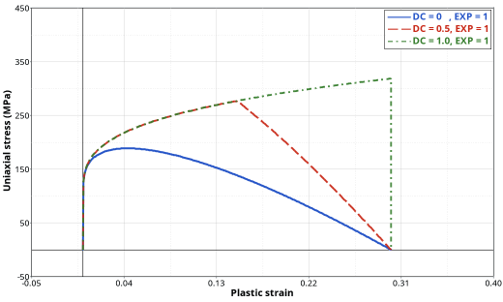
If , the stress softening starts as soon
as and the stress softening is fully
coupled (blue curve in Figure 1).
If , the stress softening is partially
coupled as it starts when (red curve).
If , the stress tensor rapidly drops to
0 when and a failure criterion approach is
then obtained (green curve).
Figure 1. Effect of stress softening parameter DC on a single
element behavior in uniaxial tension
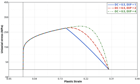
The EXP field can be used to add non-linearity in
the stress softening effect and change the shape of the stress softening
effect, as shown in Figure 2. Figure 2. Effect of stress softening exponent EXP on a single
element behavior in uniaxial tension
Note: If the DAMAGE keyword is not specified, the
damage variable only becomes an output variable without triggering any
element deletion of effect on stress computation. It can only show the
critical spots of a structure where cracks are more likely to
initiate.
The DEP_SR flag
can be used to introduce a strain rate dependency on the element failure.
This makes the material’s ductility dependent on the loading velocity. Two
possibilities are offered:
If V_TID is defined, a tabulated strain rate
dependency is defined by TABLEMD, which defines
the evolution of a dimensionless factor denoted by evolution with strain rate. Then the
strain rate effect is introduced in the damage variable evolution by
multiplication with the plastic strain at failure:(3)
Where,
Stress triaxiality
Lode parameter
V_REF
VT_SCALE
Plastic strain at failure
Strain rate
If a continuous and analytical formula is desired, the Johnson-Cook
strain rate dependency can be set up by specifying only a reference
strain rate V_REF and the parameter JC (denoted
as in the equation). Then, the damage variable evolution is given
by:(4)
Note: The strain-rate computation (total
equivalent or plastic strain rate) depends on the choice made in
the MATS1 Bulk Data Entry. In the absence of
plasticity, the strain-rate dependency is not
available.
The DEP_L flag
can be used introduce a mesh size dependency that can define the element’s
ductile behavior dependent on its initial size. This can help to reduce the
well-known mesh size dependency encountered when using coupled damage models
or failure criteria. The TABLEMD defined in
E_TID defines the evolution of a dimensionless scale
factor with the initial element size given by, . The damage evolution then
becomes:(5)
Where,
EL_REF
FE_SCALE
Both strain rate dependency and
element size dependency can be used at the same time without creating any
conflict.
Element deletion from the mesh is
activated differently depending on the element type (solid or shell) and the
formulation (under-integrated or fully integrated).
For solid elements, deletion occurs only if all the integration
points fail.
For shell elements, deletion occurs if more than half of the
integration points (over thickness) fail.
Damage initiation and evolution
failure criterion (INIEVO) can also be defined using the
DAMAGE continuation line in the MATS1 Bulk Data Entry.
For the INIEVO
criterion, strain rate dependency and element size dependency are not
available as they are already considered through the
DMGINI and DMGEVO Bulk Data
Entries. The DAMAGE keyword, DC and
EXP parameters are ignored for this criterion only.
Element deletion is always turned on and stress softening is entirely
controlled by the DMGEVO entry, if defined. If the
DMGEVO entry is not specified, a failure criterion
approach is used, and the element is deleted when the damage initiation
criterion defined by the DMGINI entry is reached.
For more information, refer to
Material Failure Criterion in
the Explicit Dynamic Analysis section of the User Guide.
1 Cuntze, R.G. and Freund, A., The predictive capability of failure mode
concept-based strength criteria for multidirectional laminates in Failure Criteria
in Fibre Reinforced Polymer Composites, 2004 QinetiQ Ltd. Published by Elsevier
Ltd.