DSHAPE
Bulk Data Entry Defines parameters for classic and grid-based free-shape design variables.
Format 1 (Classic)
| (1) | (2) | (3) | (4) | (5) | (6) | (7) | (8) | (9) | (10) |
|---|---|---|---|---|---|---|---|---|---|
| DSHAPE | ID | TYPE | |||||||
| PERT | DTYPE | MVFACTOR | NSMOOTH | MXSHRK | MXGROW | SMETHOD | NTRANS | ||
| GRID | GMETH | GSETID1/
GID1 |
GID2/ GSETID2 |
GID3/ GSETID3 |
GID4/ GSETID4 |
GID5/ GSETID5 |
GID6/ GSETID6 |
||
| GID7/ GSETID7 |
GID8/ GSETID8 |
etc | etc | ||||||
| PATRN | TYP | AID/ XA |
YA | ZA | FID/ XF |
YF | ZF | ||
| DRAW | DTYP | DAID/ XDA |
YDA | ZDA | DFID/ XDF |
YDF | ZDF | ||
| DRAFT | |||||||||
| EXTR | ECID | XE | YE | ZE | |||||
| GRIDCON | GCMETH | GCSETID1 /
GDID1 |
CTYPE1 | CID1 | X1 | Y1 | Z1 | ||
| GCMETH | GCSETID2 /
GDID2 |
CTYPE2 | CID2 | X2 | Y2 | Z2 | |||
| etc | etc | ||||||||
| SDCON | SDCID1 | XL1 | XU1 | YL1 | YU1 | ZL1 | ZU1 | ||
| SDCID2 | XL2 | XU2 | YL2 | YU2 | ZL2 | ZU2 | |||
| etc | etc | ||||||||
| BMESH | BMID | ||||||||
| FSSPLIT | SPLIT |
Format 2 (Grid-based, Vertex Morphing)
| (1) | (2) | (3) | (4) | (5) | (6) | (7) | (8) | (9) | (10) |
|---|---|---|---|---|---|---|---|---|---|
| DSHAPE | ID | TYPE | |||||||
| GRID | GMETH | ID1 | ID2 | ID3 | ID4 | ID5 | ID6 | ||
| ID7 | ID8 | etc | etc | ||||||
| PATRN | TYP | AID/XA | YA | ZA | FID/XF | YF | ZF | ||
| SID/XS | YS | ZS | |||||||
| BOUND | TOTAL/MESHF | LB | UB | ||||||
| FILTER | FTYPE | RADIUS | |||||||
| BOUNDARY | BTYPE/SETID | SKIP | |||||||
| GRIDCON | GCMETH | GCSETID1 | CTYPE2 | CID1 | X1 | Y1 | Z1 | ||
| etc | GCMETH | GCSETID2 | CTYPE2 | CID2 | X2 | Y2 | Z2 | ||
| etc | etc | ||||||||
| BMESH | BMID | ||||||||
| SMOOTH | METHOD | NLAYER | TRANS |
Definitions
| Field | Contents | SI Unit Example |
|---|---|---|
| ID | Each
DSHAPE card must have a unique ID. No default (Integer > 0) |
|
| TYPE | Free-shape
optimization type.
|
|
| PERT | Indicates perturbation information is to follow. | |
| DTYPE | Direction type for the free-shape variation.
|
|
| MVFACTOR | Initial limit on the
movement factor of the design grids. The unit of
MVFACTOR is the average mesh size of
meshes adjacent to grids defined after
GRID. Only the initial value of this limit can be set. The values in subsequent optimization iterations are automatically adjusted to enhance to enhance iterative stability and convergence speed; however, they will never be greater than the initial limit. Default = 0.5 (Real > 0.0) |
|
| NSMOOTH | Number of grids layers
NSMOOTH. Default = 10 (Integer) |
|
| MXSHRK | Maximum shrinking
distance. No default |
|
| MXGROW | Maximum growing
distance. No default |
|
| SMETHOD | Mesh smoothing
method. Method 1 is faster than method 2, but method 2 is more robust in avoiding mesh distortion. Default = 1 (1 or 2) |
|
| NTRANS | Number of design grid
layers in the transition zone to non-design area, where
additional treatment will be applied to produce smooth
transition. 1 Default = 0 (Integer ≥ 0) |
|
| GRID | Indicates that a list of grid IDs or grid sets is to follow (depending on the value of the GMETH field). These grids are design variables for the free-shape optimization. | |
| GMETH | Field indicating
whether grids are to be defined by.
|
|
| GID# | Grid identification
numbers. List of grids for which this DSHAPE
card is defined (only valid if GMETH field is
set to ID). No default (Integer > 0) |
|
| GSETID# | Grid SET
identification number. A grid set containing design grids for
free-shape optimization (only valid if GMETH
field is set to SET). No default (Integer > 0) |
|
| ID# | Identification
numbers. List of identification numbers that depend on the value
of the GMETH field in grid-based free-shape
optimization. No default (Integer > 0) |
|
| PATRN | Indicates that variable pattern grouping is active. Indicates that information about the pattern group will follow. | |
| TYP | Variable pattern
grouping type. Required if any symmetry or variable pattern
grouping is desired. 1
1-plane symmetry is supported for both CLASSIC and VERTEXM. 2- and 3-plane symmetries are available only for VERTEXM. (Integer) |
|
| AID/XA, YA, ZA | Variable pattern
grouping anchor nodes. These fields define a point that determines how grids are grouped into variables. 1 The point may be defined by entering a grid ID in the SID field or by entering X, Y, and Z coordinates in the XS, YS, and ZS fields. These coordinates are in the global coordinate system. Default = origin (Real in all three fields or Integer in AID/XA field) |
|
| FID/XF, YF, ZF | Direction of first
vector for variable pattern grouping. These fields define an xyz
vector which determines how grids are grouped into variables.
1 The X, Y, and Z coordinates are in the global coordinate system. If FID is defined, it defines a vector pointing from grid AID or point (XA, YA, and ZA) to grid FID. If XF, YF, ZF are defined, it defines a vector pointing from point (XA, YA, and ZA) to point (XA+XF,YA+YF,ZA+ZF). (XA, YA, and ZA) are coordinates of the anchor point defined by AID or XA, YA, and ZA. If all fields are blank and the TYP field is not blank or zero, OptiStruct returns an error. No default |
|
| SID/XS, YS, ZS | Direction used to
determine second vector for variable pattern grouping. 1
These fields define a xyz vector which, when combined with the first vector, form a plane. The second vector is calculated to lie in that plane and is perpendicular to the first vector. The second vector is sometimes required to determine how grids are grouped into variables. The X, Y, and Z values are in the global coordinate system. You may put a grid ID in the SID/XS field to define the second vector. This vector goes from the anchor point to this grid. If all fields are blank and the TYP field contains a value of 20 or higher, OptiStruct returns an error. No default |
|
| DRAW | Indicates that casting constraints are being applied. Indicates that draw direction information is to follow. Only valid for design grids on solid elements. | |
| DTYP | Draw direction
constraint type.
|
|
| DAID/XDA, YDA, ZDA | Draw direction anchor
point. These fields define the anchor point for draw direction
of the casting. The point may be defined by entering a grid ID
in the DAID field or by entering X, Y, and Z
coordinates in the XDA,
YDA, and ZDA fields,
these coordinates will be in the basic coordinate
system. Default = origin (Real in all three fields or Integer in first field) |
|
| DFID/XDF, YDF, ZDF | Direction of vector
for draw direction definition. These fields define a point. The
vector goes from the anchor point to this point. The point may
be defined by entering a grid ID in the DFID
field or by entering X, Y, and Z coordinates in the
XDF, YDF, and
ZDF fields, these coordinates will be in
the basic coordinate system. No default (Real in all three fields or Integer in first field) |
|
| DRAFT | Draft angle in
degrees. 2 Default = 0.0 (0.0 ≤ Real < 90.0) |
|
| SDCON# | Indicates that side constraints are being applied. | |
| SDCID# | The ID of a coordinate system which the following XL#, XU#, YL#, YU#, ZL#, or ZU# components are resolved in. | |
| XL#, XU#, YL#, YU#, ZL#, ZU# | Side constraints defined by lower and upper bounds of coordinates, which restrict the moving space of the design grids. Any of the six fields could be blank, which means the corresponding coordinate is not constrained. | |
| EXTR | Indicates that extrusion constraints are being applied. Indicates that extrusion information is to follow. Only valid for design grids on solid elements. | |
| ECID | The ID of a coordinate
system which the following X, Y, and Z components are resolved
in. For Free-Shape 9.0, only consider two simple extrusion
paths:
Default = 0 (Integer > 0) |
|
| XE, YE, ZE | When ECID is a rectangular system ID, X, Y, and Z are components of a vector under system EID, which define the extrusion path. | |
| GRIDCON | Indicates that a list
of grids with associated constraints are to follow. Note: Grids within the smoothing zone (defined by
NSMOOTH) will move during Free-shape
optimization to avoid mesh distortion without changing the
shape of the model. You can also constrain the movement of
these grids by GRIDCON even if they are
not defined after GRID.
|
|
| GCMETH | Indicates that a list
of grids is to be defined by:
|
|
| GCSETID# | Grid SET
identification numbers. IDs of certain grid SETs which are
constrained to move in a predefined manner. No default (Integer > 0) |
|
| GDID# | IDs of certain grids
which are constrained to move in a predefined manner. No default (Integer > 0, ID must also be present in the list following the GRID flag) |
|
| CTYPE# | Constraint type
applied to the grid GDID#.
No default |
|
| CID# | The ID of a coordinate
system which the following X, Y, and Z components are resolved
in. Default = 0 (Integer ≥ 0) |
|
| X#, Y#, Z# | X, Y, and Z components
of a vector, which either defines the direction in which the
grid GDID# is constrained to move, or the
normal of a plane on which the grid GDID# is
constrained to remain. Default = 0.0 (Real) |
|
| BMESH | Indicates that a BMFACE ID is to follow. | |
| BMID | The BMFACE ID which defines a list of QUADs and/or TRIAs which define a barrier that the design surface will not penetrate during shape optimization. | |
| FSSPLIT | Indicates that the design grids in the Free-Shape design space referenced by DSHAPE are split into multiple DSHAPE's, based on their normal orientation. | |
| SPLIT | Controls the splitting
of the design grids for this DSHAPE entry.
|
|
| BOUND | Indicates that shape variable bounds are to follow. | |
| TOTAL/MESHF | Character flag
indicating the bound setting way.
No default |
|
| LB | Shape design variable
lower bound. Default value = -5.0* average mesh size When TOTAL is specified, (Blank, Real ≤ 0.0) When MESHF is specified, (Blank, Real ≥ 0.0) |
|
| UB | Shape design variable
upper bound. Default value = 5.0* average mesh size (Blank, Real ≥ 0.0) |
|
| FILTER | Indicates that nodal shape sensitivities filtering options are to follow. 3 | |
| FTYPE | Filtering type of
nodal shape sensitivities. It indicates the method of nodal
shape sensitivities smoothing.
|
|
| RADIUS | Sensitivities
filtering radius. It requires a reasonable value based on
average mesh size of design domain. It is recommended that the
filter radius is not too small compared to the average mesh size
or too large compared to the whole design domain. 2 Default = 4* average mesh size (Real > 0.0) |
|
| BOUNDARY | Indicates that the boundary information of design domain is to follow. | |
| BTYPE | Boundary handling type
for shell design domain.
|
|
| SETID | Grid SET
identification number, which contains a set of non-design grids.
No default (Blank or Integer > 0) |
|
| SKIP | Boundary skip. This
parameter tells OptiStruct to skip
certain nodes out of the design domain.
|
|
| SMOOTH | Flag to indicate that the parameters for mesh smoothing method are to follow. | |
| METHOD | Mesh smoothing
method.
|
|
| NLAYER | Number of grid layers
for mesh smoothing.
Default = 10 (Integer > 0 or ALL) |
|
| TRANS | Flag to indicate a
transition zone to the non-design region.
|
Comments
- The NTRANS
option allows you to achieve a smooth transition between design and
non-design regions. This additional smoothness; however, comes with an
inherent cost of a reduction in design flexibility.
NTRANS improves design smoothness across the
transition zone between design and non-design regions at the expense of
design flexibility.
For detailed information illustrating the working mechanism of NTRANS, refer to Define Free-shape Design Regions in the User Guide.
- The draft angle can be specified in
degrees via the DRAFT field, as illustrated in Figure 1. Geometric constraints
(GRIDCON and SDCON) may not be
satisfied when the draft angle is activated:

Figure 1.
- It is required to define the nodes on the surface, as well as the nodes in the interior region as design nodes.
- For a given design node, the solver only considers its surrounding design nodes, which the distance to this given node is within RADIUS, for sensitivities filtering. RADIUS is quite significant to the final shape design. The shape change is drastic when RADIUS is small; therfeore, the model has higher local shape changes.
- For a given design node, its
smoothed sensitivity is (
), Where,Filtering factor is calculated based on FTYPE, Figure 2 shows the filter factor curves for each FTYPE. Generally filtering factor at this given node is 1.0, since it is at the center, and the node outside RADIUS has zero filtering factor.
- Filtering factor at node #i
- Sensitivity at node #i
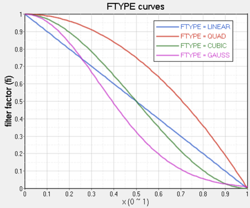
Figure 2. - For multiple disconnected design patches, it is recommended to define separate DSHAPE for each disconnected patch; however, it is not recommended to define multiple DSHAPE cards for connected design domains.
- LB and UB in BOUND continuation line are applied to each design variable, not the total magnitude of a design grid, that means the total magnitude may be beyond bounds.
- When the design domain has finer mesh and more design nodes, the optimization would take more computation time.
-
- For 1-plane symmetry (TYP =
10):The symmetry plane is defined normal to the first vector (FID/XF, YF, ZF) and is located at the anchor node (AID/XA, YA, ZA).
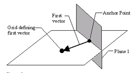
Figure 3. Defining the first symmetry plane - 2-plane symmetry (TYP =
20):
The first symmetry plane (Plane 1) is defined normal to the first vector (FID/XF, YF, ZF) and is located at the anchor node, (Figure 3).
To obtain the second symmetry plane (Plane 2), the second vector is calculated by taking the vector defined in SID/XS, YS, ZS and projecting it onto plane 1. If a grid point was used to define the second vector, the second vector is a vector running from the anchor node to the projected grid point. If a vector was used to define the second vector, the base of the projected vector is placed at the anchor point. The second vector is normal to plane 2, (Figure 4).
TYP = 20 is applicable only to VERTEXM.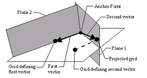
Figure 4. Defining the first and second symmetry planes - 3-plane symmetry (TYP =
30):
The first and second symmetry planes (Plane 1 and Plane 2) are determined as explained above.
Plane 3 is determined to be normal to both plane 1 and plane 2, (Figure 5).
TYP = 30 is applicable only to VERTEXM.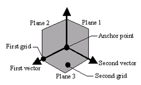
Figure 5. Defining the first, second and third symmetry planes
- For 1-plane symmetry (TYP =
10):
- This card is represented as an optimization design variables in HyperMesh.