PSHELL
Bulk Data Entry Defines the membrane, bending, transverse shear, and membrane-bending coupling of shell elements.
Format
| (1) | (2) | (3) | (4) | (5) | (6) | (7) | (8) | (9) | (10) |
|---|---|---|---|---|---|---|---|---|---|
| PSHELL | PID | MID1 | T | MID2 | 12I/T3 | MID3 | TS/T | NSM | |
| Z1 | Z2 | MID4 | T0 | ZOFFS | |||||
| EXPLICIT | ISOPE | HGID | NIP |
Example
| (1) | (2) | (3) | (4) | (5) | (6) | (7) | (8) | (9) | (10) |
|---|---|---|---|---|---|---|---|---|---|
| PSHELL | 203 | 204 | 1.90 | 205 | 1.2 | 206 | 0.8 | 6.32 | |
| +.95 | -.95 | 0.1 | |||||||
| EXPLICIT | 3 | 100 | 5 |
Definitions
| Field | Contents | SI Unit Example |
|---|---|---|
| PID | Unique simple beam property
identification.
No default (Integer > 0 or <String>) |
|
| MID1 | Material identification for membrane.
2
No default (Integer > 0 or <String>) |
|
| T | Default value for the membrane thickness (Real > 0.0). If T0 is defined for topology optimization, T is the total thickness. | |
| MID2 | Material identification for bending.
2
(Integer ≥ -1, blank or <String>) |
|
| 12I/T3 | Bending stiffness parameter. 16 Default = 1.0 (Real > 0.0 or blank) |
|
| MID3 | Material identification for transverse
shear. 2
(Integer > 0 or <String> or blank, must be blank unless MID2 > 0) |
|
| TS/T | Transverse shear thickness divided by
the membrane thickness. Default = .833333 (Real > 0.0 or blank) |
|
| NSM | Nonstructural mass per unit
area. (Real) |
|
| Z1, Z2 | Fiber distances for stress
computation. The positive direction is determined by the right hand rule and the
order in which the grid points are listed on the connection entry. (Real or blank, 7 for defaults) |
|
| MID4 | Material identification for
membrane-bending coupling. 2
(Integer > 0 or <String> or blank, must be blank unless MID1 > 0 and MID2 > 0, may not be equal to MID1 or MID2). 10 11 |
|
| T0 | The base thickness of the elements in
topology and free-size optimization. Only for MAT1,
T0 can be > 0.0. (Real ≥ 0.0 or blank for MAT1, Real = 0.0 or blank for MAT2, MAT8) |
|
| ZOFFS | Offset from the plane defined by
element grid points to the shell reference plane. Real or Character Input (Top/Bottom). 14 |
|
| EXPLICIT | Flag indicating that parameters for Explicit Analysis are to follow. | |
| ISOPE | Element formulation flag for Explicit
Analysis. 17
18
19
Default = BWC for four-noded CQUAD4 elements in explicit analysis. |
|
| HGID | Identification number of an hourglass
control (HOURGLS) entry. 20
21 Default = Blank (Integer > 0 or blank) |
|
| NIP | Number of through thickness Gauss
points. If MID2=blank and/or NIP=1, the membrane formulation is used. 23 Default = 3 (1 ≤ Integer ≤ 10) |
Comments
- The structural mass is computed from the density using the membrane thickness and membrane material properties.
- Two-dimensional elements are used to model
thin-shell or thick-shell behavior. Thin-shell behavior can be applied to situations where
transverse shear deformation in bending can be ignored (MID3 is blank),
whereas, thick-shell behavior is required in applications where transverse shear
appreciably affects model behavior. OptiStruct shell elements
have the ability to incorporate in-plane or membrane actions, plane strain, and bending
action (including transverse shear characteristics and membrane-bending coupling actions).
Reissner-Mindlin shell theory is used, by default, in OptiStruct to model shells which allow bending. MID1 cannot be blank.
Membrane Shell (Plane Stress) If MID2 is blank Membrane Shell formulation. Pure membrane in plane stress – no bending, coupling, or transverse shear stiffness. Pure membrane shell uses a standard 2D element formulation without drilling degrees of freedom. MID3 and MID4 should also be blank. 16 Membrane Shell (Plane Strain) If MID2 = -1 Membrane Shell formulation. Pure membrane in plane strain. In-plane stiffness only. No bending or transverse shear stiffness. Pure membrane shell uses a standard 2D element formulation without drilling degrees of freedom. 13 14 16 Note: Plane strain definition via this method is only supported for linear static analysis. Plane strain definition via PPLANE is more general and is supported for linear and nonlinear (small and large displacement) static analyses.Thin-Shell Formulation If MID3 is blank Thin-Shell Formulation. No transverse shear deformation is considered (this is accomplished by enforcing very high penalty on transverse shear stiffness to stop transverse shear deformation). Thick-Shell Formulation MID3 is input. Thick-Shell Formulation. Transverse shear deformation is considered. Membrane Shells are applicable in situations where out-of-plane loading is not expected. Thin-Shell formulation is generally acceptable for models, where T/L or T/W is lower than 1/20. Whereas, Thick-Shell formulations are typically valid up to 1/10 (except for the boundary layer).
Where,- T
- Shell thickness
- L
- Span of the shell
- W
- Wavelength of the deformed shape
Plasticity is supported with membrane elements (first and second order) for small and large displacement nonlinear static analysis. Among the available hardening rules in the MATS1 entry, isotropic, kinematic and mixed hardening types are supported with membrane elements.
- The continuation is not required.
- This entry is used in connection with the CTRIA3, CQUAD4, CTRIA6, and CQUAD8 entries.
- PSHELL entries may reference MAT1, MAT2, MAT4, MAT5, and MAT8 material property entries.
- The default for Z1 is -T/2, and for Z2 it is +T/2. T is the local plate thickness, defined by T on this entry. For free-sizing optimization, Z1 and Z2 definitions are ignored and the defaults of -T/2 and +T/2 are used for each element.
- If MID3 references a MAT2 material, then G33 on the MAT2 data must be blank.
- If MID3 references a MAT8 material, then G1Z and G2Z must not be blank.
- MID4 provides a way to
represent shells with offset (shell element centerline being offset from the plane of the
grid points) or shells with material properties that are not symmetric with respect to the
middle surface of the shell. However, whenever possible, the preferred method of
representing such shells is through the use of element offset ZOFFS or
the composite property PCOMP. This is because
MID4 does not provide sufficient information about the shell
structure to correctly calculate all respective results, specifically:
- The shell stresses calculated in the presence of MID4 are generally incorrect, as they do not reflect the actual shell offset or the non-uniform material structure.
- The effects of MID4 are not considered in the calculation of differential stiffness. Hence, it is recommended that MID4 be left blank in buckling analysis.
- If MID4 points to a
MAT2 card with a material ID greater than 400,000,000, then the
thermal membrane-bending coefficients A1,
A2, and A12 have a modified interpretation, and represent [G]*[alpha]
rather then [alpha].
Here, [G] is a matrix composed of G11, G22, ..., G33. This is to maintain consistency with respective terms generated internally by the PCOMP card.
- Thermal expansion coefficients provided for materials referenced as MID2 or MID3 are ignored in shell analysis - only the thermal expansion terms for materials referenced as MID1 (membrane) and MID4 (coupling) are considered. Furthermore, the reference temperature (TREF) for the shell property is taken from the material referenced as MID1 - TREF's provided for other MID's are ignored.
- Plane strain (MID2=-1) MID1 must reference a MAT1 entry.
- In plane strain computations, in-plane loads are interpreted as line loads with a value equal to the load, divided by the thickness. Thus, if a thickness of "1.0" is used, the value of the line-load equals the load value. Pressure can be approximated with multiple line loads where the pressure value equals the line-load, divided by the length between the loads.
- The shell reference plane can be offset from
the plane defined by the element nodes by means of ZOFFS. In this case
all other information, such as material matrices or fiber locations for the calculation of
stresses, is given relative to the offset reference plane. Shell results, such as shell
element forces, are output on the offset reference plane. ZOFFS can be
used in all types of analysis and optimization.ZOFFS can be input in two different formats:
- Real:
A positive or a negative value of ZOFFS is specified in this format. A positive value of ZOFFS implies that the reference plane of each shell element is offset a distance of ZOFFS along the positive z-axis of its element coordinate system.
- Surface:
This format allows you to select either "Top" or "Bottom" option to specify the offset value.
Top:
The top surface of the shell element and the plane defined by the element nodes are coplanar.
This makes the effective "Real" ZOFFS value equal to half of the thickness of the PSHELL element. (The sign of the ZOFFS value would depend on the direction of the offset with respect to the positive z-axis of the element coordinate system, as defined in the Real section).

Figure 1. Top Option in ZOFFSBottom:
The bottom surface of the shell element and the plane defined by the element nodes are coplanar.
This makes the effective "Real" ZOFFS value equal to half of the thickness of the PSHELL element. (The sign of the ZOFFS value would depend on the direction of the offset with respect to the positive z-axis of the element coordinate system, as defined in the Real section).

Figure 2. Bottom Option in ZOFFSWhen ZOFFS is used, both MID1 and MID2 must be specified; otherwise singular matrices would result.
Moreover, while offset is correctly applied in geometric stiffness matrix and thus can be used in linear buckling analysis, caution is advised in interpreting the results. Without offset, a typical simple structure will bifurcate and loose stability "instantly" at the critical load, shown in Figure 3(a). With offset though, the loss of stability is gradual and asymptotically reaches a limit load, as shown below in Figure 3(b).
Figure 3.Thus, the structure with offset can reach excessive deformation before the limit load is reached.Note: The above illustrations apply to linear buckling - in a fully nonlinear limit load simulation, additional instability points may be present on the load path.
- Real:
- The pure membrane element (in both plane stress and plane strain configurations) does not support bending. Therefore, it is susceptible to large deformation, if the direction normal to the shell is not supported. On ideally flat configurations with no out-of-plane loads, such a large deformation may be avoided without additional support. However, it is recommended to provide support in the normal direction (if the membrane shell is "skinned" on solid surfaces, then this condition is satisfied).
- The bending stiffness parameter
(12I/T3) can be defined as the ratio of the bending moment of inertia
of the shell (I) and the bending moment of inertia of a homogeneous shell
(T3/12). This parameter influences only the bending stiffness of the
shell element (for example, the displacement results due to bending and tensile loads are
presented below). The bending stiffness increases with increasing value of
12I/T3. This parameter can be used to represent non-homogeneous
material (such as honeycomb, concrete, and so on).
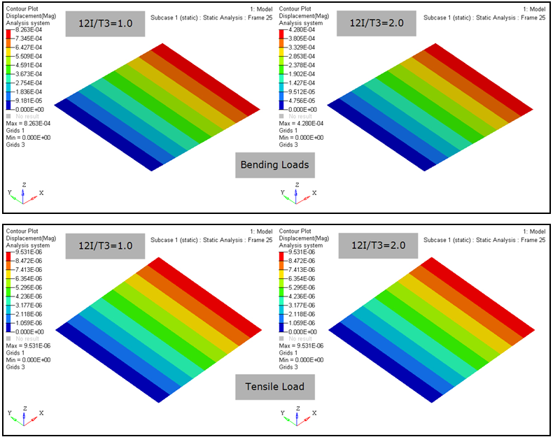
Figure 4. - For CTRIA3 Triangular elements in explicit analysis, triangular shell formulation is automatically applied. Therefore, the definition of ISOPE has no effect on CTRIA3 elements in explicit analysis.
- The Belytschko-Tsay shell formulation is very effective and robust, however, the performance is poor if the element is warped. The Belytschko-Wong-Chiang formulation is the same as Belytschko-Tsay, except the limitations in the warped configuration area is fixed with 20-30% additional computational cost.
- The Belytschko-Tsay shell and Belytschko-Wong-Chiang shell do not possess stiffness in the normal rotational degree of freedom, this would lead to singular stiffness matrix in implicit analysis. In explicit analysis, the unconstrained drilling degree of freedom usually does not create any difficulties since no stiffness matrix is required.
- For four-noded quadrilateral elements in explicit analysis, hourglass control is required to avoid spurious zero-energy modes. Triangular elements do not require hourglass control.
- Similar to PSOLID, when HGID is specified, a non-default hourglass control defined on the HOURGLS entry is chosen.
- String based labels allow for easier visual identification of properties, including when being referenced by other cards. (For example, the PID field of elements). For more details, refer to String Label Based Input File in the Bulk Data Input File.
- For explicit analysis, if MID2 is blank, then NIP is automatically reset to 1, regardless of the user input and membrane formulation is used. If MID2 is specified, and NIP is set to 1 by the user, then MID2 is ignored (this is equivalent to MID2 being blank) and again, membrane formulation is used. Therefore, for explicit analysis, if MID2=blank and/or NIP=1, then the membrane formulation is used.
- This card is represented as a property in HyperMesh.