TIE
Bulk Data Entry Defines a tied contact.
Format
| (1) | (2) | (3) | (4) | (5) | (6) | (7) | (8) | (9) | (10) |
|---|---|---|---|---|---|---|---|---|---|
| TIE | TID | PID | SSID | MSID | DOF | SRCHDIS | ADJUST | ||
| DISCRET | GSETID | ROT |
Example
| (1) | (2) | (3) | (4) | (5) | (6) | (7) | (8) | (9) | (10) |
|---|---|---|---|---|---|---|---|---|---|
| TIE | 5 | 7 | 8 | 0.01 | |||||
| N25 | 2 |
Definitions
| Field | Contents | SI Unit Example |
|---|---|---|
| TID | Tied interface
identification number. 1 (Integer > 0) |
|
| PID | Identification number of a
Property entry defined in Geometric Nonlinear Analysis ( Radioss Integration). This field is only
valid for Geometric Nonlinear Analysis
(ANALYSIS=EXPDYN). (Integer > 0) |
|
| SSID | Secondary entity
identification. 2
3
|
|
| MSID | Main entity
identification. 2
3
|
|
| DOF | Defines the
degrees-of-freedom (component numbers) that are tied together in
MPC-based TIE contact. Default = 123 (Integer, up to six unique digits (0 < digit ≤ 6) may be placed in the field with no embedded blanks for grid points. The components are in the output coordinate system referenced by the secondary grid points). |
|
| SRCHDIS | Search distance criterion
for creating contact condition. When specified, only secondary nodes
that are within SRCHDIS distance from main
surface will have contact condition checked. Default = Half of the main element size (Real > 0 or blank) For Node-to-Node (N2N) discretization, the default is 0.0. |
|
| ADJUST | Adjustment of secondary
nodes onto the main surface at the start of a simulation. 5
For Node-to-Node (N2N) discretization, the default is NO and Real value can be specified for the depth criterion, similar to other discretization types. AUTO and Integer do not apply for N2N discretization. |
|
| DISCRET | Discretization approach type for the construction of contact elements. 2 3 | |
| GSETID | Identifies a
SET entry that references grid points of the
secondary entity that are to be included in the
TIE contact regardless of the search
distance. Therefore, for any grid points identified via
GSETID, if a corresponding main surface is
available, then a corresponding TIE contact is
generated regardless of the SRCHDIS field
value. This grid set should always be a subset of the grids in the secondary entity (identified by the SSID field). The GSETID field is not
supported for N2N discretization.
(Integer > 0 or <String> or blank) |
|
| ROT | Constraining rotational
degrees of freedom for TIE contact. 13
|
Comments - Small Displacement Nonlinear Analysis
- A TIE Bulk Data Entry should have a unique ID when compared to all CONTACT Bulk Data Entries. The TIE Bulk Data Entry is internally converted to CONTACT Bulk Data with FREEZE option.
- The secondary entity
(SSID) always consists of grid nodes. It may be specified
as:
- a set of grid nodes defined using SET card
- a surface defined using SURF card (the secondary nodes are picked from the respective nodes of the SURF faces)
- a set of elements (shells or solids) defined using SET card. Secondary nodes are picked from the respective nodes of the elements in the set. For 3D solids, only nodes on the surface of the solid body are selected; internal nodes are not considered.
- OptiStruct will error out, if the structural side is set as Secondary in MPC-based TIE contact for Fluid-Structure model.
- DISCRET=N2S is recommended if the secondary entity is a set of grids (nodes) or a set of solid elements. For more information, refer to Contact Discretization in the User Guide.
- The main entity (MSID)
may be defined as:
- a surface defined using SURF card
- a set of elements (shells or solids) defined using SET card. For sets of 3D solids, element faces on the surface are automatically found and selected as main surface.
- For N2N discretization, MSID should refer to a GRID set defined by the SET entry.
- TIE element is created with the same structure as a CONTACT element of TYPE=FREEZE. TIE element enforces zero relative motion on the contact surface - the contact gap opening remains fixed at the original value and the sliding distance is forced to be zero. Also, rotations at the secondary node are matched to the rotations of the main patch. For more information, refer to Contact Discretization in the User Guide.
- For more information regarding SRCHDIS and ADJUST, refer to Contact Interface Parameters (Contact Control) in the User Guide.
- Contact stabilization for surface-to-surface contact and node-to-surface contact can be activated using the CNTSTB Subcase Information Entry and the CNTSTB Bulk Data Entry. Additionally, the PARAM, EXPERTNL Bulk Data Entry can be used to activate contact stabilization. The CNTSTB Bulk Data Entry parameters override the parameter values for a particular subcase.
- Two types of TIE contacts are available, PENALTY-based and MPC-based. The two types can be switched using CONTPRM,TIE,PENALTY/MPC. The MPC-based TIE uses multi-point constraints to define a tied contact between the main and secondary surfaces. Additionally, the MPC's can be output to <filename>_contmpc.fem using CONTPRM, CONTMPC, YES. If CONTPRM,TIE,MPC is specified, all the TIE contacts in the model are defined using the MPC-based method. For more information regarding SRCHDIS and ADJUST, refer to Lagrange Multipliers (MPC-based) in the User Guide.
- N2S option should be used to activate large shape change during shape optimization. Currently, large shape change is activated if the model has N2S contact or CGAP/CGAPG/CWELD/CFAST/CSEAM elements.
- The following table illustrates support
information for TIE contacts:
TIE Contact Linear Static Linear Transient Nonlinear Static Nonlinear Transient SMDISP LGDISP Implicit (SMDISP) Implicit (LGDISP) Explicit Penalty-based TIE Yes (Default) Yes (Default) Yes (Default) Yes (Default) Yes (Default) Yes (Default) Yes (Auto) MPC-based TIE Yes (Optional) Yes (Optional) Yes (Optional) Yes (Optional) Yes (Optional) Yes (Optional) Yes (Default) MODCHG is currently not supported for MPC-based TIE for both Small and Large Displacement Nonlinear Analysis.
- For Implicit Analysis, PENALTY-based TIE is the default. Whereas, for Explicit Analysis, MPC-based TIE is the default. For Explicit Analysis, if OptiStruct detects the model contains over-constraint conditions, then the related TIE is switched to PENALTY-based TIE automatically.
- N2N discretization is currently only supported for Small Displacement Nonlinear Analysis.
- String based labels allow for easier visual identification, including when being referenced by other entries. For more details, refer to String Label Based Input File.
- For explicit analysis where the main
side is shell, if the DRILL option is specified for
ROT field of TIE and freeze
CONTACT entries, the moment on the secondary side will be
transferred to the main nodes as forces (instead of moments) as shown below. For
Explicit Analysis with main side as solids, this is active by default and the
ROT field has no effect.
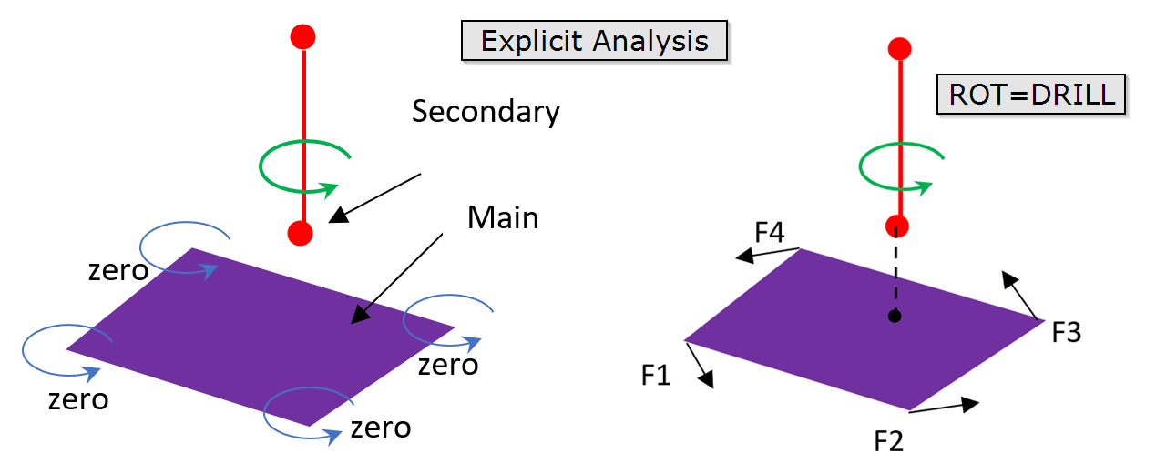
Figure 1.Information for TIE contact.TIE Contact Linear Static Linear Transient Nonlinear Static Nonlinear Transient SMDISP LGDISP Implicit (SMDISP) Implicit (LGDISP) Explicit Rotational DOF (Main side is shell) Yes (Default) Yes (Default) Yes (Default) Yes (Optional via ROT=YES) Yes (Default) Yes (Optional via ROT=YES) Yes (Optional via ROT=YES) Rotational DOF (Main side is solid) Yes (Optional) Yes (Optional) Yes (Optional) Yes (Optional via ROT=YES) Yes (Optional) Yes (Optional via ROT=YES) Yes (Default) - This card is represented as a group in HyperMesh.