PRSPENE
Bulk Data Entry Defines a pressure penetration load which can simulate fluid penetrating through the surfaces on a contact interface.
Format
| (1) | (2) | (3) | (4) | (5) | (6) | (7) | (8) | (9) | (10) |
|---|---|---|---|---|---|---|---|---|---|
| PRSPENE | SID | CTID | SPDIR | MPDIR | TRMP | ||||
| + | P1 | PCRT1 | SG1/SSET1 | FSSET1 | MG1/MSET1 | FMSET1 | |||
| + | P2 | PCRT2 | SG2/SSET2 | FSSET2 | MG2/MSET2 | FMSET2 | |||
| + | etc. |
Definitions
| Field | Contents | SI Unit Example |
|---|---|---|
| SID | Load set identification number. No default (Integer > 0) |
|
| CTID | Contact interface identification number on which the pressure
penetration load is to be applied. No default (Integer > 0) |
|
| SPDIR | Orientation of the pressure applied on the secondary surface.
Applies only to secondaries that consist of shell elements.
Secondaries defined on solid elements are always subjected to
pressure pointing inwards (which is against the default vector
normal to the element face) irrespective of this flag.
(Character) |
|
| MPDIR | Orientation of the pressure applied on the main surface.
Applies only to mains that consist of shell elements. Mains
defined on solid elements are always subjected to pressure
pointing inwards (which is against the default vector normal to
the element face) irrespective of this flag.
(Character) |
|
| TRMP | Time period over which the pressures at newly penetrated
areas are to be ramped up to the current level of a regular
load. 6 Default = 0.001 (0.0 < Real ≤ 1.0) |
|
| Pi | Pressure pool magnitude. No default (Real > 0.0) |
|
| PCRTi | Critical value of the normal contact pressure below which the
fluid can penetrate through. Default = 0.0 (Real > 0.0) |
|
| SGi/SSETi |
No default (Integer > 0) |
|
| FSSETi | Flag which indicates that the
SGi/SSETi field is
identified as a SET or a grid point.
(Characters) |
|
| MGi/MSETi |
(Blank or Integer > 0) |
|
| FMSETi | Flag which indicates that the
MGi/MSETi field is
identified as a SET or a grid point.
(Characters) |
Comments
- The pressure penetration load can simulate the behaviors of fluid pressure spreading on the surfaces of a contact interface.
- A secondary grid-based spreading strategy is adopted, which allows the fluid pressure penetrating adjacent areas on the secondary surface, starting from the initial grids specified in the SGi/SSETi field, until it gets blocked at areas where the normal contact pressure is beyond the critical value, PCRTi. On the main side, the pressure load is then applied accordingly by projecting the geometric pattern of obstacles and penetrated grids from the secondary surface. There may be main areas with no projection from the secondary detected, but are supposed to be pressurized, in such cases, the optional field MGi/MSSETi can be used that specifies the initial pressure pool properties on the main as an additional input.
- Groups of connected grid points which are divided by the obstacles can be identified as different pressure pools. Each continuation line defines the properties (initial grids, pressure magnitude and critical contact pressure) of an initial pressure pool. Multiple initial grids with different pool properties are allowed through multiple continuation lines. Pools would merge or split during the fluid penetration process. When pools with different properties merge, the largest fluid magnitude and the largest critical contact pressure value are assigned to the merged pool.
- The pressure penetration load is updated at the beginning of each nonlinear load increment and remains constant during all iterations in the increment.
- The main and the secondary sides on the contact interface must be defined as surfaces or elements SETs. Self-contact is not supported for the pressure penetration load. Contact interface of type FREEZE is not supported.
- The external force applied could
change frequently at grid points subjected to pressure penetration load. The
field, TRMP controls the time period, relative to the
entire subcase time, over which the pressures at contact status change are
to be ramped up or down. shows an example load ramping
curves of grid points which are subjected to PRSPENE
referenced by a Subcase Information Entry LOAD, in
comparison with a ramping curve of a regular LOAD. In
this example, the penetration status of the grid point changed three times
over two consecutive nonlinear static subcases. Also,
PRSPENE can be referenced by
DLOAD/TLOADi, and field
TRMP is effective in a similar way.
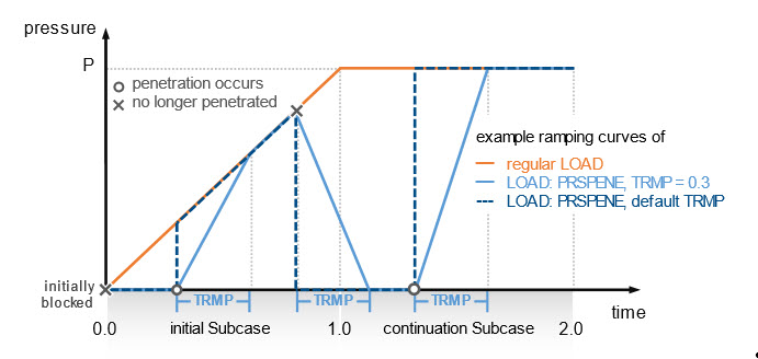
Figure 1. Example load ramping curves for a grid with pressure penetration load - PRSPENE can be referenced by TLOADx entries, similar to pressure load.
- PRSPENE is
supported for the following analysis types:
- Linear static analysis (only for TYPE=SLIDE)
- Nonlinear static analysis (small and large displacement)
- Nonlinear transient analysis (small and large displacement)
- Pressure penetration is currently
not supported for the following cases:
- 2D (axisymmetric, plane stress and plane strain) analyses
- Explicit Dynamic Analysis
- Self-contact
- Contact interface of TYPE=FREEZE