INLTVEL
Bulk Data Entry Defines the Inlet velocity for Darcy Flow Analysis.
Format
| (1) | (2) | (3) | (4) | (5) | (6) | (7) | (8) | (9) | (10) |
|---|---|---|---|---|---|---|---|---|---|
| INLTVEL | SID | EID | VALUE | G1 | G2 | G3 | G4 |
Example
| (1) | (2) | (3) | (4) | (5) | (6) | (7) | (8) | (9) | (10) |
|---|---|---|---|---|---|---|---|---|---|
| INLTVEL | 3 | 1132 | 20.0 | 2899 | 2818 | 3412 | 3422 |
Definitions
| Field | Contents | SI Unit Example |
|---|---|---|
| SID | Flow inlet velocity boundary condition set identification
number. No default (Integer > 0) |
|
| EID | Identification numbers of 2D or 3D elements on the surfaces
of which the inlet flow velocity is applied. No default (Integer > 0) |
|
| VALUE | Enforced flow velocity value on the faces of the 3D elements
or edges of 2D elements. No default (Real) |
|
| Gi | Grid identification numbers of 2D or 3D element defined via
EID. 2 Default = Blank (Integer > 0) |
Comments
- The INLTVEL Bulk Data Entry should be referenced by an INLTVEL Subcase Entry to define inlet flow boundary conditions for Darcy Flow Analysis. An SPCP Bulk/Subcase Entry pair is mandatory to activate flow analysis in steady-state heat transfer analysis. The INLTVEL Bulk/Subcase pair is optional.
- Inlet flow velocity is applied
normal to the edges of 2D elements or faces of 3D elements.
- For edges of 2D elements:
Inlet velocity is applied in the element plane and in normal direction of the edge between nodes G1 and G2, and directed towards the element center. G3 and G4 are not required when INLTVEL is applied to 2D elements.
- For faces of 3D elements: Inlet velocity is applied to the element face defined via grids G1, G2, and G3 for triangular faces and via grids G1, G2, G3, and G4 for quadrilateral faces. The inlet velocity is applied in the normal direction of the faces. For quadrilateral faces, the nodes G1, G2, G3, and G4 should be input in either clockwise or counterclockwise order (the Grid order on INLTVEL should not be arbitrary).Note: The counterclockwise ordered input below.
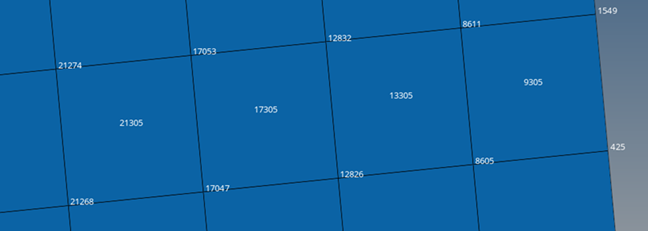
Figure 1. 3D face exampleINLTVEL 4 9305 0.2 8605 425 1549 8611 INLTVEL 4 13305 0.2 12826 8605 8611 12832 INLTVEL 4 17305 0.2 17047 12826 12832 17053 INLTVEL 4 21305 0.2 21268 17047 17053 21274
- For edges of 2D elements:
- For inlet flow conditions, there
are two options:
- Use SPCP Bulk/Subcase data to define both inlet and outlet flow pressures, leading to a definition of flow pressure differential.
- Use SPCP Bulk/Subcase data to define outlet pressure and use the INLTVEL Bulk/Subcase pair to define the inlet velocity.
- Continuation lines are not supported for INLTVEL Bulk Data Entry.