DTPL
Bulk Data Entry Defines parameters for the generation of topology design variables.
Format
| (1) | (2) | (3) | (4) | (5) | (6) | (7) | (8) | (9) | (10) |
|---|---|---|---|---|---|---|---|---|---|
| DTPL | ID | PTYPE | PID1 | PID2 | PID3 | PID4 | PID5 | PID6 | |
| PID7 | etc | etc | etc | etc | etc | etc | |||
| etc | etc |
| (1) | (2) | (3) | (4) | (5) | (6) | (7) | (8) | (9) | (10) |
|---|---|---|---|---|---|---|---|---|---|
| TMIN | T0 |
| (1) | (2) | (3) | (4) | (5) | (6) | (7) | (8) | (9) | (10) |
|---|---|---|---|---|---|---|---|---|---|
| STRESS | UBOUND |
| (1) | (2) | (3) | (4) | (5) | (6) | (7) | (8) | (9) | (10) |
|---|---|---|---|---|---|---|---|---|---|
| MEMBSIZ | MINDIM | MAXDIM | MINGAP |
| (1) | (2) | (3) | (4) | (5) | (6) | (7) | (8) | (9) | (10) |
|---|---|---|---|---|---|---|---|---|---|
| MESH | MTYP |
| (1) | (2) | (3) | (4) | (5) | (6) | (7) | (8) | (9) | (10) |
|---|---|---|---|---|---|---|---|---|---|
| DRAW | DTYP | DAID/XDA | YDA | ZDA | DFID/XDF | YDF | ZDF | ||
| OBST | OPID1 | OPID2 | OPID3 | OPID4 | OPID5 | OPID6 | OPID7 | ||
| OPID8 | etc | etc | etc | etc | etc | etc | |||
| NOHOLE | |||||||||
| STAMP | TSTAMP |
| (1) | (2) | (3) | (4) | (5) | (6) | (7) | (8) | (9) | (10) |
|---|---|---|---|---|---|---|---|---|---|
| EXTR | ETYP | ||||||||
| EPATH1 | EP1_ID1 | EP1_ID2 | EP1_ID3 | EP1_ID4 | EP1_ID5 | EP1_ID6 | EP1_ID7 | ||
| EP1_ID8 | etc | etc | etc | etc | etc | etc | |||
| etc | etc | ||||||||
| EPATH2 | EP2_ID1 | EP2_ID2 | EP2_ID3 | EP2_ID4 | EP2_ID5 | EP2_ID6 | EP2_ID7 | ||
| EP2_ID8 | etc | etc | etc | etc | etc | etc | |||
| etc | etc |
| (1) | (2) | (3) | (4) | (5) | (6) | (7) | (8) | (9) | (10) |
|---|---|---|---|---|---|---|---|---|---|
| MAIN | |||||||||
| COORD | CID | CAID/ XCA |
YCA | ZCA | CFID/ XCF |
YCF | ZCF | ||
| CSID/ XCS |
YCS | ZCS | CTID/ XCT |
YCT | ZCT |
| (1) | (2) | (3) | (4) | (5) | (6) | (7) | (8) | (9) | (10) |
|---|---|---|---|---|---|---|---|---|---|
| SECOND | DTPL_ID | ||||||||
| COORD | CID | CAID/ XCA |
YCA | ZCA | CFID/ XCF |
YCF | ZCF | ||
| CSID/ XCS |
YCS | ZCS | CTID/ XCT |
YCT | ZCT |
| (1) | (2) | (3) | (4) | (5) | (6) | (7) | (8) | (9) | (10) |
|---|---|---|---|---|---|---|---|---|---|
| COORD | CID | CAID/
XCA |
YCA | ZCA | CFID/ XCF |
YCF | ZCF | ||
| CSID/ XCS |
YCS | ZCS | CFTID/ XCT |
YCT | ZCT |
| (1) | (2) | (3) | (4) | (5) | (6) | (7) | (8) | (9) | (10) |
|---|---|---|---|---|---|---|---|---|---|
| SCALE | SX | SY | SZ |
| (1) | (2) | (3) | (4) | (5) | (6) | (7) | (8) | (9) | (10) |
|---|---|---|---|---|---|---|---|---|---|
| MATINIT | VALUE |
| (1) | (2) | (3) | (4) | (5) | (6) | (7) | (8) | (9) | (10) |
|---|---|---|---|---|---|---|---|---|---|
| PATRN | TYP | AID/ XA |
YA | ZA | FID/ XF |
YF | ZF | ||
| UCYC | SID/ XS |
YS | ZS |
| (1) | (2) | (3) | (4) | (5) | (6) | (7) | (8) | (9) | (10) |
|---|---|---|---|---|---|---|---|---|---|
| MAT | MATOPT |
| (1) | (2) | (3) | (4) | (5) | (6) | (7) | (8) | (9) | (10) |
|---|---|---|---|---|---|---|---|---|---|
| FATIGUE | FTYPE | FBOUND |
| (1) | (2) | (3) | (4) | (5) | (6) | (7) | (8) | (9) | (10) |
|---|---|---|---|---|---|---|---|---|---|
| LEVELSET | HOLEINST | HOLERAD | NHOLESX | NHOLESY | NHOLESZ |
| (1) | (2) | (3) | (4) | (5) | (6) | (7) | (8) | (9) | (10) |
|---|---|---|---|---|---|---|---|---|---|
| LATTICE | LT | LB | UB | LATSTR |
| (1) | (2) | (3) | (4) | (5) | (6) | (7) | (8) | (9) | (10) |
|---|---|---|---|---|---|---|---|---|---|
| FAILSAFE | SFAIL | DFAIL | TFAIL | DFAIL | PFAIL |
| (1) | (2) | (3) | (4) | (5) | (6) | (7) | (8) | (9) | (10) |
|---|---|---|---|---|---|---|---|---|---|
| MMAT | MID1 | MID2 | MID3 | MID4 | MID5 | MID6 | MID7 | ||
| MID8 | MID9 |
| (1) | (2) | (3) | (4) | (5) | (6) | (7) | (8) | (9) | (10) |
|---|---|---|---|---|---|---|---|---|---|
| OVERHANG | ANGLE | GID1/ X1 |
Y1 | Z1 | GID2/ X2 |
Y2 | Z2 | ||
| METHOD | STEP/ PENFAC |
PENSCHE | NONDES | HOLES | ANGTOL | DISTOL | |||
| SUPPSET |
Example 1
| (1) | (2) | (3) | (4) | (5) | (6) | (7) | (8) | (9) | (10) |
|---|---|---|---|---|---|---|---|---|---|
| DTPL | 1 | PSHELL | 7 | 8 | 17 | ||||
| MEMBSIZ | 60.0 | ||||||||
| TMIN | 1.0 |
Example 2
| (1) | (2) | (3) | (4) | (5) | (6) | (7) | (8) | (9) | (10) |
|---|---|---|---|---|---|---|---|---|---|
| DTPL | 1 | PSOLID | 4 | 5 | 6 | ||||
| MEMBSIZ | 60.0 | ||||||||
| DRAW | SPLIT | 0.0 | 0.0 | 0.0 | 1.0 | 0.0 | 0.0 | ||
| OBST | 10 | 11 | 12 |
Definitions
| Field | Contents | SI Unit Example |
|---|---|---|
| ID | Each
DTPL card must have a unique ID. No default (Integer > 0) |
|
| PTYPE | Property type or Laminate
for which the DTPL card is defined.
No default |
|
| PID# | Property or Laminate
(STACK) identification numbers. List of properties or laminates of
PTYPE for which this DTPL
card is defined. If PIDs are not listed, OptiStruct will check all properties or laminates of type PTYPE to see if they are to be included in the design space (see PCOMP, PSHELL, PSOLID, STACK, and so on). If any properties satisfy this search, then they will be affected by entries on this card. In this situation (where PIDs are not defined), only one DTPL card can be defined for the given PTYPE. Default = blank (Integer > 0 or blank) |
|
| TMIN | Indicates that minimum
thickness value will follow. Only valid when
PTYPE=PSHELL. If not present when PTYPE=PSHELL, the minimum thickness will default to the T0 value defined on the PSHELL card. If a T0 value is not defined on the PSHELL card, the minimum thickness will default to 0.0. |
|
| T0 | Minimum thickness for
PSHELL properties when the referenced
material is of type MAT1. If PSHELL references a material which is not of type MAT1, this value is ignored and T0=0.0 is used. If a value is not entered for T0, the T0 value on the PSHELL card is used. If T0 is not defined on the PSHELL card, then T0=0.0 is assumed. Default = blank (Real > 0.0) |
|
| STRESS | Indicates that stress constraints are active and that an upper bound value for stress is to follow. 1 | |
| UBOUND | Upper bound constraint on
stress. No default (Real > 0.0) |
|
| MEMBSIZ | Indicates that member size control is active for the properties listed and if MINDIM and possibly MAXDIM are to follow. | |
| MINDIM | Specifies the minimum
diameter of members formed. This command is used to eliminate small
members. It also eliminates checkerboard results. 2
Default = No Minimum Member Size Control (Real > 0.0) |
|
| MAXDIM | Specifies the maximum
diameter of members formed. This command is used to prevent the
formation of large members. Only used in combination with
MINDIM. 3 Default = No Maximum Member Size Control (Real > 0.0) |
|
| MINGAP | Defines the minimum
spacing between structural members formed. Only used in conjunction
with MAXDIM. 3 Default = blank (Real > MAXDIM) |
|
| MESH | Indicates that mesh type information is to follow. | |
| MTYP | Indicates that the mesh
conforms to certain rules for which the optimizer is tuned.
Currently, the only option available is ALIGN,
which indicates when manufacturing constraints are active, the mesh
is aligned with the draw direction or extrusion path. 4 Default = blank (ALIGN or blank) |
|
| DRAW | Indicates that casting
constraints are being applied and that draw direction information is
to follow. Only valid if PTYPE=PSOLID. OptiStruct will terminate with an error, if present for other PTYPEs. |
|
| DTYP | Draw direction constraint
type to be used.
|
|
| DAID/XDA, YDA, ZDA | Draw direction anchor
point. These fields define the anchor point for draw direction of
the casting. The point may be defined by entering a grid ID in the
DAID field or by entering X, Y, and Z
coordinates in the XDA, YDA,
and ZDA fields, these coordinates will be in the
basic coordinate system. Default = origin (Real in all three fields or Integer in first field) |
|
| DFID/XDF, YDF, ZDF | Direction of vector for
draw direction definition. These fields define a point. The vector
goes from the anchor point to this point. The point may be defined
by entering a grid ID in the DFID field or by
entering X, Y, and Z coordinates in the XDF,
YDF, and ZDF fields, these
coordinates will be in the basic coordinate system. No default (Real in all three fields or Integer in first field) |
|
| OBST | Indicates that a list of
PIDs will follow which are non-designable,
but their interaction with designable parts needs to be considered
with regards to the defined draw direction. OBST
stands for obstacle. Only recognized if DRAW flag is also present on the same DTPL card. OptiStruct will terminate with an error, if OBST flag is present without DRAW flag. |
|
| OPID# | Obstacle property
identification number. List of non-designable properties that are to
be considered with regards to the defined draw direction. These must
be PSOLID. No default (Integer > 0, blank or ALL) |
|
| NOHOLE | Prevents the formation of
through-holes in the draw direction. Note: It does not prevent holes
perpendicular to the draw direction. The assumed minimum
thickness in the draw direction is twice the average mesh
size.
|
|
| STAMP | Forcing the design to evolve into a 3D shell structure. Indicates that thickness (TSTAMP) is to follow. 5 | |
| TSTAMP | Defines the thickness of
the 3D shell structure that is evolved with the
STAMP option. The recommended minimum thickness
is three times the average mesh size. 5 No default (Real > 0.0) |
|
| EXTR | Indicates that extrusion
constraints are being applied and that extrusion information is to
follow. Only valid if PTYPE=PSOLID. OptiStruct will terminate with an error, if present for other PTYPEs. |
|
| ETYP | Extrusion constraint type
to be used.
|
|
| EPATH1 | Indicates that a list of
grid IDs will follow to define the primary extrusion path. Only recognized if EXTR flag is also present on the same DTPL card. OptiStruct will terminate with an error, if EPATH1 flag is present without EXTR flag. |
|
| EP1_ID# | Primary extrusion path
identification numbers. List of grid IDs that define the primary
extrusion path. No default (Integer > 0 or blank) |
|
| EPATH2 | Indicates that a list of
grid IDs will follow to define the secondary extrusion path. This is
only required when ETYP has been set to
TWIST. Only recognized if EXTR flag is present on the same DTPL card. OptiStruct will terminate with an error, if EPATH2 flag is present without EXTR flag. |
|
| EP2_ID# | Secondary extrusion path
identification numbers. List of grid IDs that define the secondary
extrusion path. No default (Integer > 0 or blank) |
|
| MAIN | Indicates that this design variable may be used as a main pattern for pattern repetition. 7 | |
| COORD | Indicates information regarding the coordinate system for pattern repetition is to follow. This is required if either MAIN or SECOND flag is present. | |
| CID | Coordinate system ID for a
rectangular coordinate system that may be used as the pattern
repetition coordinate system. 7 Default = 0 (Integer ≥ 0) |
|
| CAID/XCA, YCA, ZCA | Anchor point for pattern
repetition coordinate system. The point may be defined by entering a
grid ID in the CAID field or by entering X, Y,
and Z coordinates in the XCA,
YCA, and ZCA fields. These
coordinates will be in the basic coordinate system. 7 No default (Real in all three fields or Integer in first field) |
|
| CFID/XCF, YCF, ZCF | First point for pattern
repetition coordinate system. The point may be defined by entering a
grid ID in the CFID field or by entering X, Y,
and Z coordinates in the XCF,
YCF, and ZCF fields. These
coordinates will be in the basic coordinate system. 7 No default (Real in all three fields or Integer in first field) |
|
| CSID/XCS, YCS, ZCS | Second point for pattern
repetition coordinate system. The point may be defined by entering a
grid ID in the CSID field or by entering X, Y,
and Z coordinates in the XCS,
YCS, and ZCS fields. These
coordinates will be in the basic coordinate system. 7 No default (Real in all three fields or Integer in first field) |
|
| CTID/XCT, YCT, ZCT | Third point for pattern
repetition coordinate system. The point may be defined by entering a
grid ID in the CTID field or by entering X, Y,
and Z coordinates in the XCT,
YCT, and ZCT fields. These
coordinates will be in the basic coordinate system. 7 No default (Real in all three fields or Integer in first field) |
|
| SECOND | Indicates that this design variable is secondary to the main pattern definition referenced by the following DTPL_ID entry. 7 | |
| DTPL_ID | DTPL
identification number for a main pattern definition. No default (Integer > 0) |
|
| COORD | Indicates information regarding the coordinate system for pattern repetition is to follow. This is required if either MAIN or SECOND flag is present. | |
| CID | Coordinate system ID for a
rectangular coordinate system that may be used as the pattern
repetition coordinate system. 7. Default = 0 (Integer > 0) |
|
| CAID/XCA, YCA, ZCA | Anchor point for pattern
repetition coordinate system. The point may be defined by entering a
grid ID in the CAID field or by entering X, Y,
and Z coordinates in the XCA,
YCA, and ZCA fields. These
coordinates will be in the basic coordinate system. 7 No default (Real in all three fields or Integer in first field) |
|
| CFID/XCF, YCF, ZCF | First point for pattern
repetition coordinate system. The point may be defined by entering a
grid ID in the CFID field or by entering X, Y,
and Z coordinates in the XCF,
YCF, and ZCF fields. These
coordinates will be in the basic coordinate system. 7 No default (Real in all three fields or Integer in first field) |
|
| CSID/XCS, YCS, ZCS | Second point for pattern
repetition coordinate system. The point may be defined by entering a
grid ID in the CSID field or by entering X, Y,
and Z coordinates in the XCS,
YCS, and ZCS fields. These
coordinates will be in the basic coordinate system. 7 No default (Real in all three fields or Integer in first field) |
|
| CTID/XCT, YCT, ZCT | Third point for pattern
repetition coordinate system. The point may be defined by entering a
grid ID in the CTID field or by entering X, Y,
and Z coordinates in the XCT,
YCT, and ZCT fields. These
coordinates will be in the basic coordinate system. 7 No default (Real in all three fields or Integer in first field) |
|
| SCALE | This is applicable to
Pattern Repetition and Multi-Model Optimization (MMO)
functionalities. Indicates that scaling factors for pattern repetition (Main-Secondary) in a model or for Multi-Model Optimization (across multiple models) is active. |
|
| SX, SY, SZ | Scale factors for pattern
repetition or Multi-Model Optimization in X, Y, and Z directions,
respectively. 7 Default = 1.0 (Real) |
|
| COORD | Indicates information regarding the coordinate system for Multi-Model Optimization is to follow. This is required for Multi-Model Optimization runs (unless individual pattern repetition within each model is active using MAIN/SECOND continuation lines). | |
| CAID/XCA, YCA, ZCA | Anchor point for
coordinate system used in Multi-Model Optimization. The point may be
defined by entering a grid ID in the CAID field
or by entering X, Y, and Z coordinates in the
XCA, YCA, and
ZCA fields. These coordinates will be in the
basic coordinate system. 14 No default (Real in all three fields or Integer in first field) |
|
| CFID/XCF, YCF, ZCF | First point for coordinate
system used in Multi-Model Optimization. The point may be defined by
entering a grid ID in the CFID field or by
entering X, Y, and Z coordinates in the XCF,
YCF, and ZCF fields. These
coordinates will be in the basic coordinate system. 14 No default (Real in all three fields or Integer in first field) |
|
| CSID/XCS, YCS, ZCS | Second point for
coordinate system used in Multi-Model Optimization. The point may be
defined by entering a grid ID in the CSID field
or by entering X, Y, and Z coordinates in the
XCS, YCS, and
ZCS fields. These coordinates will be in the
basic coordinate system. 14 No default (Real in all three fields or Integer in first field) |
|
| CTID/XCT, YCT, ZCT | Third point for coordinate
system used in Multi-Model Optimization. The point may be defined by
entering a grid ID in the CTID field or by
entering X, Y, and Z coordinates in the XCT,
YCT, and ZCT fields. These
coordinates will be in the basic coordinate system. 14 No default (Real in all three fields or Integer in first field) |
|
| PATRN | Indicates that pattern
grouping is active for the properties listed and that information
for pattern grouping is to follow. Only valid if PTYPE=PCOMP, PSHELL, or PSOLID. OptiStruct will terminate with an error, if present for other PTYPEs. |
|
| TYP | Indicates the type of
pattern grouping requested. 10 Default = No Pattern Grouping (1, 2, 3, 9, 10, or 11) |
|
| AID/XA, YA, ZA | Anchor point for pattern
grouping. The point may be defined by entering a grid ID in the
AID field or by entering X, Y, and Z
coordinates in the XA, YA, and
ZA fields. These coordinates will be in the
basic coordinate system. 10 Default = origin (Real in all three fields or Integer in first field) |
|
| FID/XF, YF, ZF | First point for pattern
grouping. The point may be defined by entering a grid ID in the
FID field or by entering X, Y, and Z
coordinates in the XF, YF, and
ZF fields. These coordinates will be in the
basic coordinate system. 10 No default (Real in all three fields or Integer in first field) |
|
| UCYC | Number of cyclical
repetitions for cyclical symmetry. This field defines the number of
radial "wedges" for cyclical symmetry. The angle of each wedge is
computed as 360.0/UCYC. 10 Default = blank (Integer > 0 or blank) |
|
| SID/XS, YS, ZS | Second point for pattern
grouping. The point may be defined by entering a grid ID in the
SID field or by entering X, Y, and Z
coordinates in the XS, YS, and
ZS fields. These coordinates will be in the
basic coordinate system. 10 No default (Real in all three fields or Integer in first field) |
|
| MATINIT | Continuation line to define the DTPL-dependent initial material fraction. | |
| VALUE | Default = 0.9 for
optimization with mass as the objective, Default is reset to the
constraint value for runs with constrained mass. If mass is not the
objective function and is not constrained, then the default is
0.6.
This continuation line takes precedence over DOPTPRM,MATINIT for this design variable. |
|
| MAT | Indicates the type of composite topology optimization. Only considered for PTYPE=PCOMP. | |
| MATOPT |
|
|
| FATIGUE | Indicates that fatigue constraints are active and their definitions are to follow. | |
| FTYPE | Fatigue constraint
type.
|
|
| FBOUND | Specifies the bound
value. If FTYPE=DAMAGE, FBOUND will be the upper bound of fatigue damage. If FTYPE=LIFE or FOS, FBOUND will be the lower bound of fatigue life (LIFE) or Factor of Safety (FOS), respectively. No default (Real) |
|
| LEVELSET | Indicates that the Level Set method (for topology optimization) is activated and the definitions of the required parameters follow. 23 - 27 | |
| HOLEINST | Method used to insert holes into the design.
|
|
| HOLERAD | <REAL NUMBER> A real
number that specifies the initial radius of the holes.
Default = 5 times the average mesh size |
|
| NHOLESX / NHOLESY / NHOLESZ | <POSITIVE INTEGER> A
positive integer that specifies the number of holes in X
direction (when HOLEINST=
ALIGN).
NHOLESY and NHOLESZ can be inferred by analogy. |
|
| LATTICE | Indicates that Lattice Structure Optimization is activated and the definitions of the required parameters are to follow. | |
| LT | Lattice type (only
applicable to hexahedral elements). For other element types
(tetrahedron, pyramid, and pentahedron), there is only one lattice
type and it is active by default. 11
12 Default = 1 (Integer: 1, 2, 3, or 4) |
|
| LB | Density lower bound. 11
12 Default = 0.1 (0.0 ≤ Real ≤ 1.0) |
|
| UB | Density upper bound. 11
12 Default = 0.8 (0.0 ≤ Real ≤ 1.0) |
|
| LATSTR | Stress constraint for
Phase 2 of Lattice Optimization (see Stress Constraints in the User Guide). No default (Real) |
|
| FAILSAFE | Indicates that Failsafe Topology Optimization is activated and the definitions of the required parameters are to follow. 13 | |
| SFAIL | Size of the individual
Failure Zones in a particular layer. This is the edge length for
CUBE failure zone (see
TFAIL) and the diameter for
SPHERE. No default (Real > 0.0) |
|
| DFAIL | Distance (spacing) between
Failure Zones in a particular layer. This is the distance between
the center of one failure zone to the next. Default = SFAIL (Real > 0.0) |
|
| TFAIL | Failure Zone type.
|
|
| OFAIL | Activates the Overlap
(second) Failure Zone in addition to the first Failure zone.
|
|
| PFAIL | Defines the ratio
(fraction) of total design volume below which the volume is not
considered as a Damage Zone. Default = 0.0 (Real > 0.0) |
|
| MMAT | Indicates that Multiple Materials Topology Optimization is activated and the definitions of the required parameters are to follow. 15 | |
| MAT# | Candidate material
identification numbers. List of candidate materials used for
multiple material optimization. 16 No default (Integer > 0 or blank) |
|
| OVERHANG | Indicates that Overhang Constraints are active and the definitions of the required parameters are to follow. | |
| ANGLE | Orientation angle for the
Overhang Constraint. This angle is measured from the build
direction, and a larger angle implies more design freedom. No default (Real ≥ 0.0) |
|
| GID1, GID2 | Grid point identification
numbers which identify the orientation. The orientation can also be
identified by defining coordinates (X#,
Y#, Z#). Default = Blank (Integer > 0) |
|
| X#, Y#, Z# | Coordinates of two points
which identifies the orientation. Default = Blank (Real) |
|
| METHOD | Overhang Constraint
Method. 20
|
|
| STEP/ PENFAC |
|
|
| PENSCHE | Penalization scheme. 17
|
|
| NONDES | Indicates if the
non-design area is supported or unsupported.
|
|
| HOLES | Indicates if the holes are
supported or unsupported.
|
|
| ANGTOL | Tolerance angle which
identifies the elements of the design space for which the overhang
constraint is not applied. The identified layer will be assumed as
supported by the optimizer. 21 Default = 90.0 (0.0 ≤ Real ≤ 90.0)
Note: For
ANGTOL=90.0, only the first layer of
elements on the surface of the model (encountered when
traveling in the build direction) is
supported.
|
|
| DISTOL | Distance which
characterizes the layer of design space for which the overhang
constraint is not applied. The identified layer will be assumed as
supported by the optimizer. 21
Default = 0.0 (Real ≥ 0.0)
Note: For
DISTOL=0.0, only the first layer of
elements on the surface of the model (encountered when
traveling in the build direction) is
supported.
|
|
| SUPPSET | References the
identification number of a SET of grid points which identifies
regions of the model that are considered to be supported. Default = Blank (Integer > 0) |
Comments
- The von Mises stress constraints may be
defined for topology and free-size optimization through the
STRESS optional continuation line on the
DTPL or the DSIZE card. There are a number of restrictions with this constraint:
- The definition of stress constraints is limited to a single von Mises permissible stress. The phenomenon of singular topology is pronounced when different materials with different permissible stresses exist in a structure. Singular topology refers to the problem associated with the conditional nature of stress constraints, that is, the stress constraint of an element disappears when the element vanishes. This creates another problem in that a huge number of reduced problems exist with solutions that cannot usually be found by a gradient-based optimizer in the full design space.
- Stress constraints for a partial domain of the structure are not allowed because they often create an ill-posed optimization problem since elimination of the partial domain would remove all stress constraints. Consequently, the stress constraint applies to the entire model when active, including both design and non-design regions, and stress constraint settings must be identical for all DSIZE and DTPL cards.
- The capability has built-in intelligence to filter out artificial stress concentrations around point loads and point boundary conditions. Stress concentrations, due to boundary geometry are also filtered to some extent as they can be improved more effectively with local shape optimization.
- Due to the large number of elements with active stress constraints, no element stress report is given in the table of retained constraints in the .out file. The iterative history of the stress state of the model can be viewed in HyperView or HyperMesh.
- Stress constraints do not apply to 1D elements.
- Stress constraints may not be used when enforced displacements are
present in the model.Note: The functionality of the STRESS continuation line to define topology stress constraints consists of many limitations. It is recommended to use DRESP1-based Stress Responses. Actual Stress Responses for Topology and Free-Size (Parameter) Optimization are available through corresponding Stress response RTYPE's on the DRESP1 Bulk Data Entry. The Stress-NORM aggregation is internally used to calculate the Stress Responses for groups of elements in the model.
- It is recommended that a
MINDIM value be chosen such that it is at least 3 times,
and no greater than 12 times, the average element size. When pattern grouping,
draw direction, or extrusion constraints are active, a MINDIM
value of 3 times the average element size is enforced, and user-defined values
(which are smaller than this value) will be replaced by this value. However, in
cases where a MINDIM greater than 12 times the average
element size is defined, irrespective of whether, or not other manufacturing
constraints are defined, the value is reset to be equal to 12 times the average
element size. If DOPTPRM,TOPDISC is
present in the model, a MINDIM value equal to 2 times the
average element size is enforced.
If MINDIM is defined, but no other manufacturing constraint exists, MINDIM will not be reset to the recommended lower bound value for PTYPE=PSHELL or PSOLID, if the defined value is less than the recommended value. For PTYPE=PCOMP, MINDIM will be reset in the absence of manufacturing constraints.
- MAXDIM should be at
least twice the value of MINDIM. If the input value of
MAXDIM is too small, OptiStruct automatically resets the value and an INFORMATION message is printed.
The MAXDIM constraint introduces significant restriction to the design problem. Therefore, it should only be used when it is a necessary design requirement. A study without MAXDIM should always be carried out in order to compare the impact of this additional constraint.
MAXDIM implies the application of a MINGAP constraint of the same value as MAXDIM, as well. Therefore, for MINGAP to be effective, it should be greater than MAXDIM.
It is important to pay attention to volume fraction as the achievable volume is below 50% when MAXDIM is defined, and further decreases as MINGAP increases.
- MTYP=ALIGN may be used in
conjunction with draw direction or extrusion manufacturing constraints to
indicate that a mesh is aligned with a draw direction or extrusion path.
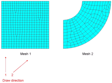
Figure 1. Draw DirectionMesh 1 is "aligned" for draw direction 1 in the example shown, but not for draw direction 2.
MTYP=ALIGN may also be used in conjunction with manufacturing constraints (minimum member, maximum member, pattern grouping, and pattern repetition) other than draw direction and extrusion, and Mesh 1 is considered "aligned" for those manufacturing constraints, too.
In both cases, this will enable OptiStruct to use a smaller minimum member size and smaller maximum member sizes. The default minimum member size is three times the average element edge length; with an "aligned" mesh, the default size can be two times the average element edge length.
Mesh 2 in the example shown is not "aligned" in any case.
- The stamping constraint is available for
only one sheet, which is defined by the combination of STAMP
and DTYP as SINGLE.
It is recommended that the stamping thickness, TSTAMP, be chosen such that it is at least 3 times the average element size. If TSTAMP is defined less than the minimum recommended value, TSTAMP will be reset to the minimum recommended value.
STAMP and NOHOLE can be a good combination as this helps to produce a continuous/spread shell structure.Note: Attention should be paid to the compatibility between thickness and target volume. - Extrusion constraints cannot be combined with draw direction constraints.
- Pattern repetition allows similar regions
of the design domain to be linked together so as to produce similar topological
layouts. This is facilitated through the definition of "Main" and "Secondary"
regions. A DTPL card may only contain one
MAIN or SECOND flag. Parameters will
not be exported for any DTPL cards containing the
SECOND flag. For both "Main" and "Secondary" regions, a
pattern repetition coordinate system is required and is described following the
COORD flag. To facilitate reflection, the coordinate
system may be a left-handed or right-handed Cartesian system. The coordinate
system may be defined in one of two ways, listed here in order of precedence:
- Four points are defined and these are utilized as follows to define the
coordinate system (this is the only way to define a left-handed system):
- A vector from the anchor point to the first point defines the x-axis.
- The second point lies on the x-y plane, indicating the positive sense of the y-axis.
- The third point indicates the positive sense of the z-axis.
- A rectangular coordinate system and an anchor point are defined. If only an anchor point is defined, it is assumed that the basic coordinate system is to be used.
Multiple "Secondary" may reference the same "Main."
Scale factors may be defined for "Secondary" regions, allowing the "Main" layout to be adjusted via the SCALE continuation line.
For a more detailed description, refer to Pattern Repetition contained within the User Guide section Topology Optimization Manufacturability.
- Four points are defined and these are utilized as follows to define the
coordinate system (this is the only way to define a left-handed system):
- Pattern grouping is applicable for PCOMP, PSHELL, and PSOLID components only.
- For historic reasons, the SYMM flag may be used in place of the PATRN flag.
- Currently there are six pattern grouping
options:
1-plane symmetry (TYP=1)
This type of pattern grouping requires the anchor point and first point to be defined. A vector from the anchor point to the first point is normal to the plane of symmetry.
2-plane symmetry (TYP=2)
This type of pattern grouping requires the anchor point, first point, and second point to be defined. A vector from the anchor point to the first point is normal to the first plane of symmetry. The second point is projected normally onto the first plane of symmetry. A vector from the anchor point to this projected point is normal to the second plane of symmetry.
3-plane symmetry (TYP=3)
This type of pattern grouping requires the anchor point, first point, and second point to be defined. A vector from the anchor point to the first point is normal to the first plane of symmetry. The second point is projected normally onto the first plane of symmetry. A vector from the anchor point to this projected point is normal to the second plane of symmetry. The third plane of symmetry is orthogonal to both the first and second planes of symmetry, passing through the anchor point.
Uniform Pattern Grouping (TYP=9)
This type of pattern grouping does not require any additional input. It only requires the TYP field to be set equal to 9. All elements included in this DTPL entry are automatically considered for uniform pattern grouping. All elements on this DTPL entry are set equal to the same element density with respect to one another.
Cyclic (TYP=10)
This type of pattern grouping requires the anchor point, first point, and number of cyclical repetitions to be defined. A vector from the anchor point to the first point defines the axis of symmetry.
Cyclic with symmetry (TYP=11)
This type of pattern grouping requires the anchor point, first point, second point, and number of cyclical repetitions to be defined. A vector from the anchor point to the first point defines the axis of symmetry. The anchor point, first point, and second point all lay on a plane of symmetry. A plane of symmetry lies at the center of each cyclical repetition.
For a more detailed description, refer to Pattern Grouping contained within the User Guide section Topology Optimization Manufacturability.
- The LT field can be used to specify the lattice type used in Lattice Structure Optimization for hexahedral elements.
- The density thresholds are defined using the LB and UB fields on the LATTICE continuation line. Elements with densities below LB (real) are considered voids and removed for the second phase. Elements with densities above UB (real) are considered solid and are retained as solid elements for the second phase. Elements with densities between LB and UB are considered as porous phases and elements having these densities are replaced by lattice structures. The amount of intermediate densities (between 0.0 and 1.0) is controlled using DOPTPRM, POROSITY. Refer to Lattice Structure Optimization in the User Guide for further information.
- FailSafe topology optimization runs in
SPMD mode and requires the
-fsoscript option. Refer to Failsafe Topology Optimization in the User Guide for further information. - Multi-Model Optimization requires the
definition of the COORD continuation line to allow mapping of
the design domains among multiple models. If individual pattern repetition is
defined on all models, then this continuation line is not required as the
COORD data from the pattern repetition section is used
instead. The coordinate system can be defined in one of two different ways:
- Four points are defined, and these are utilized as follows to define the
coordinate system (this is the only way to define a left-handed
system):
A vector from the anchor point to the first point defines the x-axis.
The second point lies on the x-y plane, indicating the positive sense of the y-axis.
The third point indicates the positive sense of the z-axis.
- A rectangular coordinate system and an anchor point are defined. If only an anchor point is defined, it is assumed that the basic coordinate system is to be used.
- Four points are defined, and these are utilized as follows to define the
coordinate system (this is the only way to define a left-handed
system):
- Both solids and shells are supported in
multiple materials topology optimization. The following two limitations apply to
PSHELLs in the design space for multiple materials
topology optimization.
- For any PSHELL entry part of the design space, then all material reference fields (MID# fields) on each PSHELL entry should point to the same material entry.
- Additionally, if multiple PSHELL entries are part of the design space, then all MID# fields on all PSHELL entries should point to the same material entry.
- The original material defined by its property will be taken as one of the candidate material by default. Besides the original one, the maximum number of candidate materials is nine (9). Only isotropic material MAT1 is supported on the MID# fields.
- The Rational Approximation for Material
Properties (RAMP) method uses the following equation for
penalization.
(1) Where,- Penalized stiffness matrix of an element (as a function of density)
- Actual stiffness matrix of an element
- Density
- Penalization factor
For information about Solid Isotropic Material with Penalty (SIMP) method, see the Design Elements section.
- For overhang constraints, STEP=1 allows aggressive move limits and typically converges fast. It generally produces good results for a majority of situations. However, it may show large fluctuations in convergence. In such cases, STEP=2 can be tried, which moves conservatively and follows a smoother convergence curve. It may sometimes offer faster convergence and better designs.
- This card is represented as an optimization design variable in HyperMesh.
- If the METHOD field
is set to CONSTR, then the following considerations are
available:
- Depending on the model, CONSTR method can pose a significant reduction of the design freedom for the optimization. Which may lead to a reduction in performance compared to the run without overhang constraints.
- If a volume or mass constraint is used in addition to the overhang constraint with CONSTR, then the target may be too low for the optimizer to find a good design. In such cases, you can try increasing the volume or mass target.
- If the impact on the performance or the volume/mass target is too large, then try the PENALTY method.
If the METHOD field is set to PENALTY, then the following considerations are available:- This method is good at removing members that are overhanging but have a small or medium impact on the performance. This method may not remove members which are very important to performance. If the goal is to remove such high impact members, try the CONSTR method instead.
- For PENALTY method, the violations of overhang angle are output to H3D file.
- The ANGTOL and
DISTOL fields can be used to define elements that are
considered to always be supported during optimization. Candidate elements are
all those elements in the first layer encountered when traveling in the build
direction. If this layer is inclined more than ANGTOL, and
lies within DISTOL, it is always supported.The elements which are always supported are output to the H3D file under the “Predefined Support” results type. For the actual manufacturing of the part, some sections of this predefined support might require support structure.
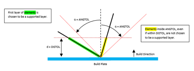
Figure 2. - LATPRM,LATSUP can be used to define the maximum volume fraction of the lattice support regions when overhang constraints are used in Topology Optimization.
- The level set method can merge existing holes but cannot nucleate new holes in the design domain, unless TOPDER is defined. Therefore, creating an initial design with holes is necessary, especially for 2D design problems (For 3D design problems, new holes can be “tunneled” when two surfaces merged).
- By default, OptiStruct will automatically create a Cheese-like
initial design with holes adaptively distributed over the design domain (Figure 3) The default hole radius is 5.0 times
the average mesh size.
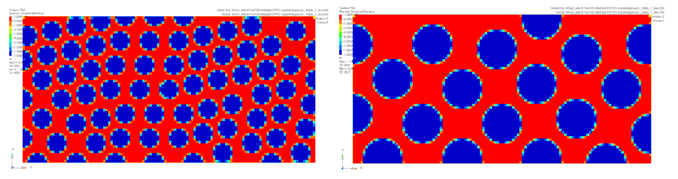
Figure 3. A Cheese-like Initial Design Generated . (left) with default setting; (right) double hole radius - Changing the value of
HOLERAD can result in different initial designs. Figure 3(right) shows an initial design filled with holes
possessing a doubled hole radius when compared to Figure 3(left). If you want to create an initial design with
evenly distributed and well aligned holes (this may be preferable for regular
design domains), HOLEINST can be set to
ALIGN. The number of holes in each direction can be further
specified by using NHOLESX, NHOLESY and
NHOLESZ (Figure 4).
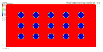
Figure 4. A Cheese-like Initial Design with 3-by-5 Evenly Distributed Holes . (generated using: HOLEINST=ALIGN, NHOLESX=5 and NHOLESY=3) - The Radial draw direction option allows
you to define manufacturing constraints for draw such that the die can be
withdrawn in a radially outward direction away from the cylindrical axis defined
by DAID → DFID. The Spherical draw
direction option allows you to define manufacturing constraints for draw such
that the die can be withdrawn in a spherically outward direction away from the
central point defined by DAID. The anchor grid for spherical
draw direction is recommended to be placed in the center of geometry.
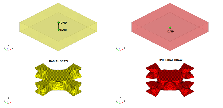
Figure 5. Radial and Spherical Draw Direction - For more information, refer to Level Set Method in the User Guide.
- This card is represented as an optimization designvariable in HyperMesh.