JOINTG
Bulk Data Entry Defines a joint connection between two grids.
Format
| (1) | (2) | (3) | (4) | (5) | (6) | (7) | (8) | (9) | (10) |
|---|---|---|---|---|---|---|---|---|---|
| JOINTG | JID | JPID | JTYPE | GID1 | CID1 | GID2 | CID2 |
Example
| (1) | (2) | (3) | (4) | (5) | (6) | (7) | (8) | (9) | (10) |
|---|---|---|---|---|---|---|---|---|---|
| JOINTG | 2 | 3 | UNIVERSA | 234 | 1 | 2445 | 1 |
Definitions
| Field | Contents | SI Unit Example |
|---|---|---|
| JID | Joint element
identification number. No default (Integer > 0) |
|
| JPID | Property identification
number of PJOINTG. Default = Blank (Integer > 0) |
|
| JTYPE | Joint type. 2
Combination Joints: Any combination of the following
translational joints: AXIA,
INLI, RLIN,
CART, INPL, RPIN
can be assembled with any of the rotational joints:
ORIE, CARD,
ROTA to create a combination joint.
Note: translational joints always should be listed first,
followed by the rotational joint (as shown in the examples
below, and in the table).
No default |
|
| GID1 | Grid Point identification
number of the first grid. No default (Integer > 0) |
|
| CID1 | Coordinate system
identification number for the first grid point
GID1. Default = blank (Integer > 0) |
|
| GID2 | Grid Point identification
number of the second grid. No default (Integer > 0) |
|
| CID2 | Coordinate system
identification number for the second grid point
GID2. Default = blank (Integer > 0) |
Comments
- JOINTG element identification numbers should be unique compared to any other element in OptiStruct.
- The following table provides information
regarding currently supported Motion (MOTNJG), Loading
(LOADJG), stop/lock (PJOINTG) degrees
of freedom.
Joint Type Motion (MOTNJG) Load (LOADJG) Stop/Lock (PJOINTG) Constrained degrees of freedom Elasticity (PJOINTG) RIGID (PJOINTG) DAMP (PJOINTG) CREF (PJOINTG) CID1 CID2 AXIAL 1 1 1 1 1 YES YES NO NO BALL 2.a/2.b 123 YES NO NO RPIN 2.a2.b 123 YES YES NO CARTESIA 123 123 123 123 YES* YES YES NO INLINE 1 1 23 YES YES NO INPLANE 23 1 YES YES NO CARDAN 456 YES YES NO ORIENT 456 YES YES YES REVOLUTE 4 4 56 YES YES YES UNIVERSA 5 (twist) YES YES YES HINGE2.d 4 4 12356 4 (ELAS only) YES YES YES YES RLINK 1 (AXIAL) YES NO NO RBEAM 123456 YES NO NO UJOINT 1235 YES YES YES CYLINDRI 14 14 14 2356 14 14 YES YES YES YES TRANSLAT 1 1 1 23456 1 1 YES* YES YES YES ROTATION 456 456 456 456 456 YES* YES YES NO Example Combination Joints 2.e AXIAORIE 1 1 1 456 1 1 YES* YES YES YES INLICARD 1456 1 23 YES YES YES RLINORIE 1 (axial) 456 YES YES YES CARTROTA 123456 123456 123456 123456 123456 YES* YES YES NO INPLORIE 23 23 23 1456 23 23 YES* YES YES YES CARTORIE 123 123 456 123 123 YES* YES YES YES RPINROTA 456 456 456 123 456 456 YES* YES YES NO CARTCARD 123456 123456 123456 123456 123456 YES* YES YES NO *Supported only for Explicit Dynamic Analysis (NLEXPL).
- For BALL joint, there is no relative translation between the two degrees of freedom in the basic system. Local systems should not be defined for the BALL joint and will not be used if specified.
- For RPIN
joint, there is no relative translation between the grids in the local
system defined on CID1 (this is where
RPIN differs from BALL joint).
Note: For any local system defined on a grid for the joints, the local systems move/rotate along with the grids on which they are defined.Therefore, even though from the perspective of the basic system, there may seem to be relative translation between the grids in RPIN joint, there will not be any relative translation between the grids in the local CID1 which moves/rotates with grid GID1.
- Constrained degrees of freedom are degrees of freedom of each grid of the joint that allow no relative motion with each other in that dof. For example, in BALL joint, no relative motion is allowed in degrees of freedom 123 between the two grids of the joint.
- CID2 for HINGE joint is mandatory only for LGDISP and only if the JOINTG grids are non-coincident.
- Combination joints listed in the table above are examples. Any combination of the following translational joints: AXIA, INLI, RLIN, CART, INPL can be assembled with any of the rotational joints: ORIE, CARD, ROTA to create a combination joint. The translational joints always should be listed first, followed by the rotational joint (as shown in the examples).
- In the case of Explicit Dynamic Analysis, MOTNJG and LOADJG are not supported. STOP/LOCK, DAMP, ELASTICITY and RIGID options are supported for certain joints, as summarized above.
- For additional information regarding the joint definitions, refer to JOINTG (Connectors) in the User Guide.
- JOINTG support
information:
- JOINTG is supported for Linear Static, Small Displacement Nonlinear Static, Large Displacement Nonlinear Static, Direct Transient, and Inertia Relief solution sequences.
- MOTNJG (zero and non-zero motion) and LOADJG are supported for all relevant joints and solution sequences for which JOINTG is supported (with some exceptions). For linear analysis, only MOTNJG with zero-motion is supported. MOTNJG with non-zero motion is only supported for CYLINDRICAL and AXIAL joints in SMDISP. LOADJG is supported only for CYLINDRICAL and AXIAL joints in SMDISP.
- STOP/LOCK on PJOINTG entry is only supported for LGDISP and SMDISP Nonlinear Static Analysis (NLSTAT).
- Force, Displacement, Reaction Forces, Viscous Damping Forces, and Stop/Lock Status results for JOINTG are output to the <filename>.joint file when OPTI file format is chosen on STRESS and STRAIN I/O Entries, respectively. If H3D file format is requested on STRESS and STRAIN entries, then the corresponding results are labeled as JOINTG Force and JOINTG Disp., JOINTG Reaction Forces (s), JOINTG Viscous Forces (s), and JOINTG Stop and Lock Status (s), respectively. Note that Viscous Damping Forces are output only if the PROPERTY field on PJOINTG is set to DAMP.
- Over-constraint check information is
printed in the .out file when JOINTG
degrees of freedom are over-constrained. This is currently only available when
the JOINTG entry is in the model, and if multiple constraints
apply on the same degree of freedom. These multiple enforced constraints create
a loop, which is now printed in the .out file, allowing you
to identify such grid points. In Figure 1, a loop can be seen as:2003 → 9003 → 1003 → 2003
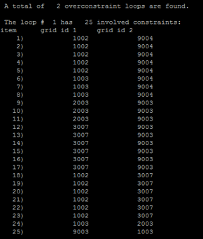
Figure 1. - The OptiStruct joints defined using JOINTG are different from the Multibody Dynamics (OS-MBD) joints which are defined using the JOINT entry with OptiStruct-MotionSolve integration.