CONTACT
Bulk Data Entry Defines a contact interface.
Format
| (1) | (2) | (3) | (4) | (5) | (6) | (7) | (8) | (9) | (10) |
|---|---|---|---|---|---|---|---|---|---|
| CONTACT | CTID | PID/ TYPE /MU1 |
SSID | MSID | MORIENT | SRCHDIS | ADJUST | CLEARANCE | |
| DISCRET | TRACK | CORNER | ROT | SORIENT |
| (1) | (2) | (3) | (4) | (5) | (6) | (7) | (8) | (9) | (10) |
|---|---|---|---|---|---|---|---|---|---|
| + | SMOOTH | SMSIDE | SMREG |
| (1) | (2) | (3) | (4) | (5) | (6) | (7) | (8) | (9) | (10) |
|---|---|---|---|---|---|---|---|---|---|
| + | PSURF | PSID1 | PSID2 |
| (1) | (2) | (3) | (4) | (5) | (6) | (7) | (8) | (9) | (10) |
|---|---|---|---|---|---|---|---|---|---|
| + | COHE | MCOHEDID | COHEGSET |
| (1) | (2) | (3) | (4) | (5) | (6) | (7) | (8) | (9) | (10) |
|---|---|---|---|---|---|---|---|---|---|
| + | ACTIVA | IDS1 | IDM1 | ||||||
| IDS2 | IDM2 | ||||||||
| + | DEACTIVA | IDS5 | IDM6 | ||||||
| IDS7 | IDM7 | ||||||||
| + | PCONT | MSID1 | SSID1 | PID1 | |||||
| MSID2 | SSID2 | PID2 | |||||||
| etc. | etc. | etc. | |||||||
| + | PSURF | SID1 | PSID1 | ||||||
| SID2 | PSID2 |
Example 1
| (1) | (2) | (3) | (4) | (5) | (6) | (7) | (8) | (9) | (10) |
|---|---|---|---|---|---|---|---|---|---|
| CONTACT | 5 | SLIDE | 7 | 8 | |||||
| N2S |
Example 2
| (1) | (2) | (3) | (4) | (5) | (6) | (7) | (8) | (9) | (10) |
|---|---|---|---|---|---|---|---|---|---|
| CONTACT | 5 | SLIDE | 7 | 8 | |||||
| S2S | |||||||||
| SMOOTH | SECONDARY | 71 | |||||||
| SMOOTH | SECONDARY | 72 | |||||||
| SMOOTH | MAIN | ALL |
Example 3 (Auto-Contact)
| (1) | (2) | (3) | (4) | (5) | (6) | (7) | (8) | (9) | (10) |
|---|---|---|---|---|---|---|---|---|---|
| CONTACT | 23 | AUTO | |||||||
| ACTIVA | ALL | ||||||||
| PSURF | ALL | 11 |
Definitions
| Field | Contents | SI Unit Example |
|---|---|---|
| CTID | Contact interface
identification number. (Integer > 0) |
|
| PID | Property identification of
a PCONT or PCONTX entry.
(Integer > 0 or <String> (only for PCONT)) |
|
| TYPE | Choose type of contact
without pointing to contact property - respective default property
settings will be used. Default settings can be changed using CONTPRM. 4
|
|
| MU1 | Coefficient of static
friction (
). 5 (0.0 ≤ Real < 1.0) |
|
| SSID | Secondary entity
identification. 1
2
10
|
|
| MSID | Main entity
identification. 1
2
10
|
|
| MORIENT | Orientation of contact
"pushout" force from main surface. Applies only to mains that
consist of shell elements or patches of grids. Mains defined on
solid elements always push outwards irrespective of this flag. 6
19
Default = OPENGAP (if TRACK is not set to FINITE/CONSLI) or NORMAL (if TRACK=FINITE/CONSLI) |
|
| SRCHDIS | Search distance criterion
for creating contact condition. When specified, only secondary nodes
that are within SRCHDIS distance from main
surface will have contact condition checked. 6 Default = Twice the average edge length on the main surface. For FREEZE contact, half the average edge length. (Real > 0 or blank) For Node-to-Node (N2N) discretization, the default is 0.0 |
|
| ADJUST | Adjustment of secondary
nodes onto the main surface at the start of a simulation. 6
For Node-to-Node (N2N) discretization, the default is NO and Real value can be specified for the depth criterion, similar to other discretization types. AUTO and Integer do not apply for N2N discretization. |
|
| CLEARANCE |
|
|
| DISCRET | Discretization approach type for the construction of contact elements. 1 | |
| TRACK | Activates Finite-Sliding
contact. 10
|
|
| ROT | Constraining rotational
degrees of freedom for N2S and S2S FREEZE contact. 24
|
|
| SORIENT | Orientation of contact
force applied on the secondary surface (which should be in the same
direction as the pushout force from the main surface). This field is
only applicable to S2S contact with CONSLI. 19
|
|
| CORNER | Corner treatment for the
secondary surface of N2S and S2S contacts. 12
|
|
| SMOOTH | Continuation lines for surface smoothing definition flag. 6 | |
| SMSIDE | Main and/or Secondary
side(s) of the contact interface to be smoothed. 6
No default |
|
| SMREG | Specifies the region at
the Main/Secondary surface to be smoothed. 6
|
|
| PSURF | Continuation line for surface property assignment. Only supported for explicit analysis. | |
| PSID1 | The
PSURF entry ID which is used to define the
secondary surface property. No default (Integer > 0) |
|
| PSID2 | The
PSURF entry ID which is used to define the
main surface property. No default (Integer > 0) |
|
| COHE | Continuation line for cohesive material. 18 | |
| MCOHEDID | Identification number of
MCOHED card that is referenced by the current
contact. No default (Integer > 0) |
|
| COHEGSET | Cohered grid set. 14
|
|
| ACTIVA | Flag indicating that the following fields indicate the surfaces for which the auto-contact is activated. 20 21 | |
| IDSi |
No default |
|
| IDMi |
No default |
|
| DEACTIVA | Flag indicating that the following fields indicate the surfaces for which the auto-contact is to be deactivated. 20 22 | |
| IDSi |
No default |
|
| IDMi |
No default |
|
| PCONT | Flag indicating that the following fields reference contact interfaces to which the corresponding PCONT PID applies. | |
| MSIDi |
No default |
|
| SSIDi |
No default |
|
| PIDi | References the
identification number of a PCONT entry. No default (Integer > 0) |
|
| PSURF | Flag indicating that the following fields reference contact interfaces to which the corresponding PSURF PIDs apply. | |
| SIDi |
No default |
|
| PSIDi | References the identification number of PSURF entries. |
Comments
- A general set of guidelines for
secondary/main selection are:
- Select the surface with finer mesh as the secondary and the other as the main.
- Select the smaller surface as the secondary and the other as the main.
- Select the softer surface as the secondary and the other as the main.
For information regarding choosing between N2S and S2S contact, refer to Contact Discretization in the User Guide.
- The secondary entity
(SSID) always consists of grid nodes. It may be specified
as:
- A set of grid nodes defined using SET(GRID, ..) command
- A surface defined using SURF command (the secondary nodes are picked from the respective nodes of the SURF faces)
- A set of elements (shells or solids) defined using SET(ELEM, ..) command. Secondary nodes are picked from the respective nodes of the elements in the set. For 3D solids, only nodes on the surface of the solid body are selected; internal nodes are not considered.
DISCRET=N2S is recommended if the secondary entity is a set of grids (nodes) or a set of solid elements.
- The main entity
(MSID) may be defined as:
- A surface defined using SURF command.
- A set of elements (shells or solids) defined using SET(ELEM, ..) command. For sets of 3D solids, element faces on the surface are automatically found and selected as main surface.
- The MSID can be left blank or set the same as SSID to activate Self Contact condition. This is currently supported only for Node-to-Surface (N2S) and Surface-to-Surface (S2S) contact with Continuous Sliding (CONSLI). For further information, refer to Self-Contact in the User Guide.
- For N2N discretization, MSID should refer to a GRID set defined by the SET entry.
- For information on the different contact interfaces (TYPE field options), refer to Contact Interface Types in the User Guide.
- MU1 directly on the
CONTACT card allows for simplified specification of
frictional contacts.Note: This implies MU2=MU1, unless MU2 is specified explicitly on the CONTPRM card. Also, the value of MU1 assigned on the CONTACT card must be less than 1.0 - to specify higher values of static coefficient of friction, the PCONT card must be used.
If FRIC is not explicitly defined on the PCONTX/PCNTX# entries, the MU1 value on the CONTACT or PCONT entry is used for FRIC in the /INTER entries for Explicit Dynamic Analysis. Otherwise, FRIC on PCONTX/PCNTX# overwrites the MU1 value on CONTACT/PCONT. For further information regarding frictional contact, refer to Friction in the User Guide.
- For information regarding the different contact parameters (ADJUST, CLEARANCE, MORIENT, TRACK, SMOOTH, SRCHDIS, GPAD), refer to Contact Interface Parameters (Contact Control) in the User Guide.
- Contact stabilization for Surface-to-Surface Contact and Node-to-Surface contact can be activated using the CNTSTB Subcase Information and CNTSTB Bulk Data Entries. Additionally, PARAM, EXPERTNL,CNTSTB can be used to activate contact stabilization. The CNTSTB Bulk Data parameters override the parameter values for a particular subcase.
- Thermal-structural analysis problems involving contact are fully coupled since contact status changes thermal conductivity. For further information, refer to Contact-based Thermal Analysis in the User Guide.
- Applying rotational SPC on nodes which belong to a FREEZE contact should be avoided. Fixing the rotational degrees of freedom will prevent the rotation of these contact nodes even in the case of solid elements.
- Finite Sliding (TRACK=FINITE) option is currently supported only if TYPE=SLIDE or if friction (via MU1/CONTPRM/PCONT) is defined. For further information, refer to Finite Sliding (TRACK) in the User Guide.
- In continuous-sliding contact (TRACK=CONSLI), the contact search is conducted for every contact iteration. In the formulation of contact virtual work, every term is updated based on the status in current iteration. The contact tangent stiffness matrix is computed in a consistent way. Continuous-sliding contact is expected to produce more accurate results and in some cases, better convergence robustness, especially when very large sliding and/or distortion are present.
- Corner treatment is supported for N2S (only for TRACK=CONSLI) and S2S (for all TRACK options) contacts. When corner treatment is turned on (AUTO or Real value), the contact surface around a secondary node may be divided into several continuous surface patches if break angle criteria are satisfied on one or more edges at the node. For each surface patch, a separate contact element will be created for the element stiffness matrix, element force vector and element history variables computation. Corner treatment may improve robustness and accuracy in some cases.
- The CONTACT entry
is supported for:
- Linear and Nonlinear Static Analysis
- Linear and Nonlinear Transient Analysis
- Linear Dynamic Analysis
- Heat Transfer Analysis
- Contact-based Thermal Analysis (HEAT)
- Explicit Dynamic Analysis (EXPDYN)
- N2S option should be used to activate large shape change during shape optimization. Currently, large shape change is activated if the model has N2S contact or CGAP/CGAPG/CWELD/CFAST/CSEAM elements.
- N2N discretization is currently only supported for Small Displacement Nonlinear Analysis.
- The following comments apply to
Edge-to-Edge contact via PSURF field.
- PSURF field is only supported for explicit analysis.
- The secondary side must be surface-based (cannot be grid-based).
- PSURF should be defined for both secondary and main.
- Shell boundary edges are not currently supported.
- Axisymmetric and plane-strain
contacts are supported for axisymmetric elements (CQAXI,
CTAXI, and CTRIAX6 elements) and
plane-strain solid elements (CQPSTN and
CTPSTN elements). The SURF
entry can be used to define the Main and Secondary surfaces. Axisymmetric and plane-strain contacts are currently supported for:
- SMALL (small sliding) for both N2S and S2S discretization
- CONSLI (continuous sliding) for N2S discretization
Axisymmetric and plane-strain contacts are not supported for:- FINITE (finite sliding)
- CONSLI (continuous sliding) for S2S discretization
- Surface Smoothing
- Cohesive contact works only for small-sliding (TRACK=SMALL), frictionless (TYPE=SLIDE or MU1=0.0) N2S/S2S contact.
- In case of implicit analysis, the
shell contact surface orientation must be user-defined.
In case of explicit analysis, the shell contact surface orientation is automatically detected. Thus, the user does not need to define consistent orientations on the surface.
- Auto-Contact is activated by setting the TYPE field to AUTO and is only applicable to Explicit Dynamics (NLEXPL) analysis. ACTIVA continuation line is used to activate auto-contact, and DEACTIVA continuation line is used to deactivate certain contact interfaces from auto-contact. PCONT and PSURF continuation lines can be used to correspondingly activate Contact Properties and Edge Criteria for contact interfaces and surfaces.
- For ACTIVA, if
both IDSi and IDMi are defined, then
OptiStruct will internally generate components
based on these surfaces and detect all possible contact among them. For example, if you define:
+, ACTIVA, 1, 2
 +, , 3, 4
Then internally separate components are created based on surfaces 1, 2, 3, and 4. Contact is then automatically detected between these components. Self-contact inside each component is also detected.
Each surface can include multiple components (even the entire model can be a single surface). Internally, components are created for any defined surfaces. Component here implies a topologically connected geometry, like a bolt. Therefore, two separate bolts will be treated as two components even if they are defined as a single surface.
- DEACTIVA is
specifically intended to disable unwanted contact inside the model. For example, if you define:
 +, DEACTIVA, 1, 2
 +, , 3, 4
Then contacts between faces in surface 1 and surface 2 are deactivated. Similarly, contact between faces in surface 3 and surface 4 are also deactivated. Self-contact within surface 1 and self contact within surface 2 and so on will not be deactivated. Additionally, contact between surfaces 1 and 3, or contact between surface 1 and 4, etc will not be deactivated.
To explicitly deactivate self-contact for a particular surface, for instance, surface 1, then the following line can be added:+, DEACTIVA, 1, 2 +, , 3, 4 +, ,1,1If there are any contact interfaces defined via Standard CONTACT or TIE entries, they will automatically be excluded in Auto-contact. For example,+, ACTIVA, ALL TIE,100,1,2The contact between surfaces 1 and 2 are excluded. An exception to this is that these exclusions occur only if surfaces 1 and 2 are defined in the ELFACE format. If the surface 1 is a nodal SET, then such surfaces are not excluded.
- String based labels allow for easier visual identification, including when being referenced by other entries. For more details, refer to String Label Based Input File.
- For explicit analysis where the main
side is shell, if the DRILL option is specified for
ROT field of TIE and freeze
CONTACT entries, the moment on the secondary side will be
transferred to the main nodes as forces (instead of moments) as shown below. For
explicit analysis with main side as solids, this is active by default and the
ROT field has no effect.
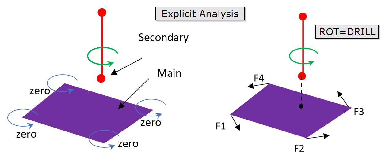
Figure 1.Information for TIE contact.TIE Contact Linear Static Linear Transient Nonlinear Static Nonlinear Transient SMDISP LGDISP Implicit (SMDISP) Implicit (LGDISP) Explicit Rotational DOF (Main side is shell) Yes (Default) Yes (Default) Yes (Default) Yes (Optional via ROT=YES) Yes (Default) Yes (Optional via ROT=YES) Yes (Optional via ROT=YES) Rotational DOF (Main side is solid) Yes (Optional) Yes (Optional) Yes (Optional) Yes (Optional via ROT=YES) Yes (Optional) Yes (Optional via ROT=YES) Yes (Default) - This card is represented as a group in HyperMesh.