FATSEAM
Bulk Data Entry Used to define parameters and property identification data for Seam Weld Fatigue Analysis.
Format
| (1) | (2) | (3) | (4) | (5) | (6) | (7) | (8) | (9) | (10) |
|---|---|---|---|---|---|---|---|---|---|
| FATSEAM | ID | WTYPE | REFEID | WLDSIDE | |||||
| PSHELL | PID1 | PID2 | etc | etc | etc | etc | PID7 | ||
| PID8 | PID9 | etc | |||||||
| ELSET | SETID1 | SETID2 | SETID3 | SETID4 | SETID5 | SETID6 | SETID7 | ||
| SETID8 | SETID9 | SETID10 | etc |
Definitions
| Field | Contents | SI Unit Example |
|---|---|---|
| ID | Each
FATSEAM card must have a unique ID. No default (Integer > 0) |
|
| WTYPE | Weld type.
No default |
|
| REFEID | Reference element
identification number. 3 Default = blank (Integer > 0) |
|
| WLDSIDE | Weld side. 4
(Integer) |
|
| PSHELL | Indicates that the following property fields reference PSHELL entries. | |
| PIDi | Property identifier of
weld elements. 1 No default (Integer > 0) |
|
| ELSET | Indicates the following fields reference element SET IDs. | |
| SETIDi | Element SET ID of weld
elements. 1 No default (Integer > 0) |
Comments
- For the Volvo method
(METHOD=VOLVO on
FATPARM), the seam weld elements should be modeled with
CQUAD4 or CTRIA3 elements only that
reference PSHELL properties. CTRIA3
elements should only be used for corner or end closing. For the Volvo method,
both PSHELL and ELSET continuation lines
can be used to identify the weld elements. In the case of
ELSETs, they should only reference sets of
CQUAD4 or CTRIA3 elements that
reference PSHELLs.
For the Joint Line method (METHOD=JNTLINE on FATPARM), the seam weld elements should be modeled with PLOTEL elements only. The FATDEFnode numbering of the PLOTELs is not relevant and the PLOTEL elements only serve to identify the weld line and do not structurally affect the solution. For the Joint Line method, only the ELSET continuation line can be used to identify the set(s) of PLOTEL elements.
- The FATDEF Bulk Data Entry may reference this identifier via the FATSEAM continuation line.
- REFEID defaults are
governed by the following conditions:
- If WTYPE is set to T, REFEID is mandatory.
- If WTYPE is set to L, and there are three shell plates joined at the weld line, then REFEID is mandatory.
- WLDSIDE defaults
are governed by the following conditions:
- If WTYPE is set to T, GENERIC, and BUTT, then WLDSIDE is not mandatory.
- If WTYPE is set to L and there are three shell plates joined at the weld line, then WLDSIDE is mandatory.
- If WTYPE is set to L and there are two shell plates joined at the weld line, and WLDSIDE is blank, then the weld is located at the smaller angle side of the two shell plates.
- If specified,
REFEID and WLDSIDE are used together
to identify the direction in which the weld exists. REFEID
identifies an element connected to the weld line, and WLDSIDE
identifies the direction of the weld, with respect to the element normal of the
element identified via REFEID. Figure 1 can help clarify how the weld
location is identified. EVALDIS is the evaluation distance
specified on the PFATSMW entry.
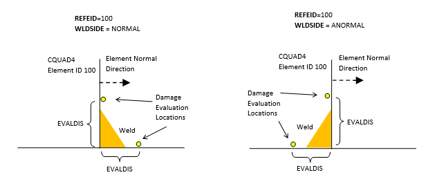
Figure 1. L Fillet Joint Example (WTYPE=L)