*surfacecreateruled
Create surfaces that interpolates linearly or smoothly between input lines.
Syntax
*surfacecreateruled line_list_id link_coords_array number_of_link_coords guide_mark_id ruled_type options comp_mode
Type
HyperMesh Tcl Modify Command
Description
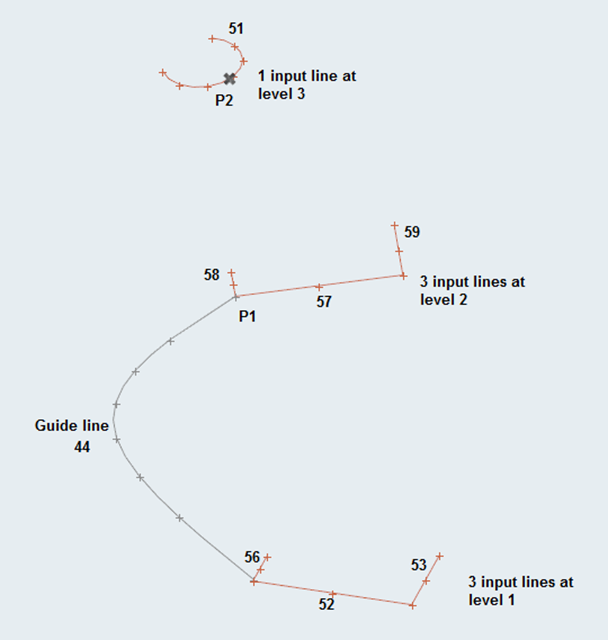
This command creates surfaces by interpolating linearly or smoothly between input lines. Optionally, a list of linking points and/or guiding lines can be provided for better interpolation and shape control. The input lines should be given in the correct order, grouped into ‘levels’ of the ruled surface. For example, referring to the image below, the input line list should first include 3 lines at level 1, then 3 lines at level 2 and then the line at level 3.
Inputs
- line_list_id
- The ID of the list containing the input lines. Valid values are 1 and 2.
- link_coords_array
- The list of x-, y- and z-coordinates for the optional points which are to be linked by an edge in the ruled surface(s). Link points should be given in pair or points, since each link between input lines is specified by its two end points. When these points are given, the final ruled surfaces include a surface edge that connects these points. Because of that, the pair of points must not skip levels. For instance, in the image below, we cannot skip level 2 by connecting a point at level 1 with a point at level 3. If such a skip is detected, the corresponding pair of points is ignored. One point may be linked to multiple points at a level above or below it, which results in creation of ‘triangular’ surfaces.
- number_of_link_coords
- The size of the link_coords_array.
- guide_mark_id
- The ID of the mark containing the guiding lines. Valid values are 1 and 2.
- ruled_type
- 0 - Smooth interpoloation
- options
- Flags that indicate different modes for surface creation. Bit values are used and the
value is calculated as (Bit0 + 2*Bit1):
- Bit0
- 0 - Merge surfaces at shared input lines
- Bit1
- 0 - Create open-ended ruled surfaces
- comp_mode
- 0 - Surfaces are created in the current component
Examples
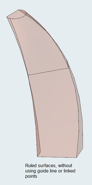
Referring to the images above, to create linear ruled surfaces between lines 56, 52, 53, 58, 57, 59 and 51, without using any guide lines or linked points:
*createlist lines 1 56 52 53 58 57 59 51
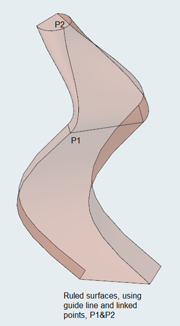
*surfacecreateruled 1 1 0 2 1 0 0To create smooth ruled surfaces interpolating lines 56, 52, 53, 58, 57, 59 and 51 with the following conditions: ruled surface will be in the input lines component; split at the input lines; links point P1 = (2.3, 4.5, 6.0) and point P2 = (12.3, 2.25, 36.30), uses guide lines 44:
*createlist lines 1 56 52 53 58 57 59 51
*createdoublearray 6 2.3 4.5 6.0 12.3 2.25 36.30
*createmark lines 2 44
*surfacecreateruled 1 1 6 2 0 3 1
Errors
if { [ catch {command_name...} ] } {
   # Handle error
}
Version History
2019